EIR-OPS-006.3: EPS/BAT Health Check
Objective
To complete EPS and battery health checks of the satellite.
Introduction
This procedure will assess the health of the EPS and battery to ensure they are functional following launch.
Procedure
This procedure has two sub procedures. Sub-procedure A is to be performed outside of a communication pass, as the communication passes are to be optimised for downlinking data and performing real-time assessment of the state of the spacecraft.
A. Assessment of Downlinked Data
A.1.
Assess any PASCAL data previously downlinked from the spacecraft. If none of this data type has been downlinked yet, set up an LDT to do this as part of EIR-OPS-003: Start a Communication Pass procedure. Some things to consider are when assessing the data are:
How has the charging rate of the spacecraft behaved since launch? e.g. are the four solar panels charging the battery at the expected rates during eclipse and sunlight? How rapidly does the charge rate drop on entering an eclipse?
Have nominal battery levels been maintained since launch? where…
Battery Details
Battery Voltage
Status
7.5-8.2V
Nominal
6.1-7.5V
Safe Mode
<6.1V
Spacecraft turns off.
Are the current draws of the buses as expected? If so, have they been as expected since launch?
B. EPS/BAT Realtime Health Checks
Important
You are about to send the first TC of this procedure - Have you completed the EIR-OPS-003: Start a Communication Pass procedure? A Communication Pass must be started prior to carrying out the operations planned for the pass. Don’t forget to open and set up the parameters/actions that will be used during the pass in MCS before the pass begins!
Warning
Operators should only begin steps to turn on PDMs in the different sections (i.e. GMOD, FSS, EMOD) below if at least 1 minute still remains until LOS.
Tip
After turning off PDMs, Operators should be aware that in some cases it may take several tens of seconds for the switch currents and voltages to return to the values previously observed when they were powered off. This is normal as long as the currents/voltages have decreased significantly from the powered on values and also appear to be decreasing.
B.1.
To check the expected state of all the PDMs,
Getthe parameterplatform.EPS.expectedSwitchStateswithFirst row= 0 andLast row= 9.
TC Details |
|
MCS Operation |
|
Action/Param Name |
|
Data Expected with TC |
Yes |
Data Size |
4 bytes, 4 bytes |
Data Info |
|
Allowed Value(s) |
0-9, 0-9 |
Expected Value(s) |
0, 9 |
TM Details |
|
Data Expected from TC |
List of switch states ( + ACK) |
Data Size |
List[0:10] of Booleans |
Data Info |
If 0, a PDM is off. If 1, a PDM is on. |
Allowed Value(s) |
0 or 1 for each switch state |
Expected Value(s) |
0,0,0,0,0,0,0,0,0,1 (only EMOD PDM/PDM 10 on) - As in Figure 1 below |
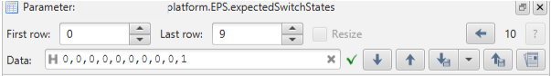
Figure 1 - MCS screenshot of platform.EPS.expectedSwitchStates outputs, detailing the states of all the PDMs.
B.2.
To check the actual state of all the PDMs,
Getthe parameterplatform.EPS.actualSwitchStateswithFirst row= 0 andLast row= 9.Compare these results to the expected switch states obtained in Step B.1.
Caution
The FSS is drawing parasitic power on PDM8/Row7 of EPS.actualSwitchStates and so will always be returned as 1 (ON), even if the state of PDM8/Row7 of EPS.expectedSwitchStates is set to 0 (OFF). In the case of PDM8, the parameter EPS.actualSwitchStates cannot be used to verify the state of PDM8.
TC Details |
|
MCS Operation |
|
Action/Param Name |
|
Data Expected with TC |
Yes |
Data Size |
4 bytes, 4 bytes |
Data Info |
|
Allowed Value(s) |
0-9, 0-9 |
Expected Value(s) |
0, 9 |
TM Details |
|
Data Expected from TC |
List of switch states ( + ACK) |
Data Size |
List[0:10] of Booleans |
Data Info |
If 0, a PDM is off. If 1, a PDM is on. |
Allowed Value(s) |
0 or 1 for each switch state |
Expected Value(s) |
0,0,0,0,0,0,0,1,0,1 (PDMs 8 and 10 on) - As in Figure 2 below |
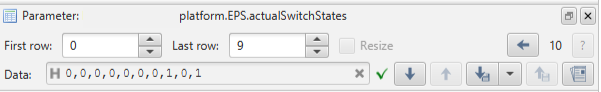
Figure 2 - MCS screenshot of platform.EPS.actualSwitchStates outputs, detailing the states of all the PDMs.
B.3.
To turn off the EMOD PDM (i.e. PDM 10),
Setthe parameterplatform.EPS.expectedSwitchStateswithFirst row= 9 andLast row= 9 to 0.
Important
If EMOD has been turned off prior to this, and PDM10/ROW9 of EPS.expectedSwitchStates is already 0, proceed to step B.5.
TC Details |
|
MCS Operation |
|
Action/Param Name |
|
Data Expected with TC |
Yes |
Data Size |
4 bytes, 4 bytes, boolean |
Data Info |
|
Allowed Value(s) |
0-9, 0-9, 0-1 |
Expected Value(s) |
9, 9, 0 |
TM Details |
|
Data Expected from TC |
No ( + ACK) |
B.4.
Getthe parameterplatform.EPS.actualSwitchStateswithFirst row= 0 andLast row= 9.Ensure that PDM 10/row 9 is now off/0.
Caution
The FSS is drawing parasitic power on PDM8/Row7 of EPS.actualSwitchStates and so will always be returned as 1 (ON), even if the state of PDM8/Row7 of EPS.expectedSwitchStates is set to 0 (OFF). In the case of PDM8, the parameter EPS.actualSwitchStates cannot be used to verify the state of PDM8.
TC Details |
|
MCS Operation |
|
Action/Param Name |
|
Data Expected with TC |
Yes |
Data Size |
4 bytes, 4 bytes |
Data Info |
|
Allowed Value(s) |
0-9, 0-9 |
Expected Value(s) |
0, 9 |
TM Details |
|
Data Expected from TC |
List of switch states ( + ACK) |
Data Size |
List[0:10] of Booleans |
Data Info |
If 0, a PDM is off. If 1, a PDM is on. |
Allowed Value(s) |
0 or 1 for each switch state |
Expected Value(s) |
0,0,0,0,0,0,0,1,0,0 (PDM 8 on only)- As in Figure 3 below |
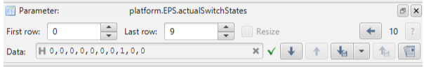
Figure 3 - Screenshot of MCS expected platform.EPS.actualSwitchStates outputs when all PDMs are switched off.
B.5.
To next assess the PDM voltages,
Getthe parameterplatform.EPS.switchVoltageswithFirst row= 0 andLast row= 9.Ensure the voltages of all PDMs (bar PDM 8) are low (i.e. ~0003), which further supports that the PDMs are off.
Caution
The FSS is drawing parasitic power so PDM8/Row7 of EPS.switchVoltages is expected to have a value ~250 and not ~0003.
TC Details |
|
MCS Operation |
|
Action/Param Name |
|
Data Expected with TC |
Yes |
Data Size |
4 bytes, 4 bytes |
Data Info |
|
Allowed Value(s) |
0-9, 0-9 |
Expected Value(s) |
0, 9 |
TM Details |
|
Data Expected from TC |
List of switch voltages ( + ACK) |
Data Size |
List[0:10] of Integers |
Data Info |
Voltage measurement for the switches |
Allowed Value(s) |
0000 - FFFF (hex) for each switch voltage |
Expected Value(s) |
PDMs 0-7,9 and 10 ~ 0003, PDM8 ~ 250 - As in Figure 4 below |
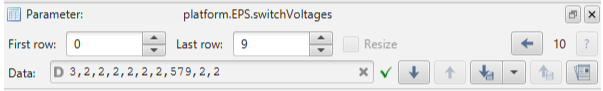
Figure 4 - MCS screenshot of expected platform.EPS.switchVoltages outputs when all PDMs are switched off.
B.6.
Now
Getthe parameterplatform.EPS.switchCurrentswithFirst row= 0 andLast row= 9.Ensure the currents are all low (i.e. ~ 0003), which again further supports that the PDMs are off.
TC Details |
|
MCS Operation |
|
Action/Param Name |
|
Data Expected with TC |
Yes |
Data Size |
4 bytes, 4 bytes |
Data Info |
|
Allowed Value(s) |
0-9, 0-9 |
Expected Value(s) |
0, 9 |
TM Details |
|
Data Expected from TC |
List of switch currents ( + ACK) |
Data Size |
List[0:10] of Integers |
Data Info |
Current measurement for the switches |
Allowed Value(s) |
0000 - FFFF (hex) for each switch currents |
Expected Value(s) |
~0003 - As in Figure 5 below |
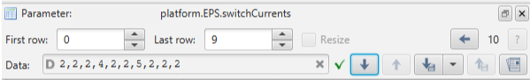
Figure 5 - MCS screenshot of low platform.EPS.switchCurrents demonstrating all PDMs are off.
GMOD PDMs
B.7.
To next assess the health of the GMOD PDMs,
Invoketheplatform.EPS.TurnOnGMODaction to turn on GMOD.
TC Details |
|
MCS Operation |
|
Action/Param Name |
|
Data Expected with TC |
No |
TM Details |
|
Data Expected from TC |
No ( + ACK) |
B.8.
To ensure all the GMOD PDMs are now on,
Getthe parameterplatform.EPS.actualSwitchStateswithFirst row= 0 andLast row= 9.Ensure that PDMs 3, 6 and 9/rows 2, 5 and 8 are all 1.
Caution
The FSS is drawing parasitic power on PDM8/Row7 of EPS.actualSwitchStates and so will always be returned as 1 (ON), even if the state of PDM8/Row7 of EPS.expectedSwitchStates is set to 0 (OFF). In the case of PDM8, the parameter EPS.actualSwitchStates cannot be used to verify the state of PDM8.
TC Details |
|
MCS Operation |
|
Action/Param Name |
|
Data Expected with TC |
Yes |
Data Size |
4 bytes, 4 bytes |
Data Info |
|
Allowed Value(s) |
0-9, 0-9 |
Expected Value(s) |
0, 9 |
TM Details |
|
Data Expected from TC |
List of switch states ( + ACK) |
Data Size |
List[0:10] of Booleans |
Data Info |
If 0, a PDM is off. If 1, a PDM is on. |
Allowed Value(s) |
0 or 1 for each switch state |
Expected Value(s) |
0,0,1,0,0,1,0,1,1,0 - As in Figure 6 below |
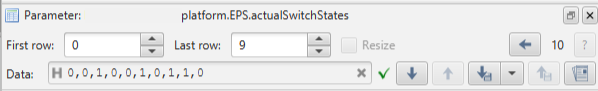
Figure 6 - MCS screenshot of expected platform.EPS.actualSwitchStates output when GMOD is turned on.
B.9.
Getthe parameterplatform.EPS.switchVoltageswithFirst row= 0 andLast row= 9.Ensure the voltages for PDMs 3, 6 and 9 (Rows 2, 5 and 8) are in the ranges 683 - 922, 843 - 862 and 757 - 773 respectively, indicating those PDMs are now on.
Caution
The FSS is drawing parasitic power so PDM8/Row7 of EPS.switchVoltages is expected to have a value ~250 and not ~0003.
TC Details |
|
MCS Operation |
|
Action/Param Name |
|
Data Expected with TC |
Yes |
Data Size |
4 bytes, 4 bytes |
Data Info |
|
Allowed Value(s) |
0-9, 0-9 |
Expected Value(s) |
0, 9 |
TM Details |
|
Data Expected from TC |
List of switch voltages ( + ACK) |
Data Size |
List[0:10] of Integers |
Data Info |
Voltage measurement for the switches |
Allowed Value(s) |
0000 - FFFF (hex) for each switch voltage |
Expected Value(s) |
PDMs 3, 6 and 9 > 0003 - As in Figure 7 below |
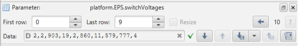
Figure 7 - MCS screenshot of expected platform.EPS.switchVoltages output when GMOD is turned on.
B.10.
Getthe parameterplatform.EPS.switchCurrentswithFirst row= 0 andLast row= 9.Ensure the currents for PDMs 3, 6 and 9 are higher than in Step B.6, also indicating those PDMs are on.
TC Details |
|
MCS Operation |
|
Action/Param Name |
|
Data Expected with TC |
Yes |
Data Size |
4 bytes, 4 bytes |
Data Info |
|
Allowed Value(s) |
0-9, 0-9 |
Expected Value(s) |
0, 9 |
TM Details |
|
Data Expected from TC |
List of switch currents ( + ACK) |
Data Size |
List[0:10] of Integers |
Data Info |
Current measurement for the switches |
Allowed Value(s) |
0000 - FFFF (hex) for each switch currents |
Expected Value(s) |
PDMs 3, 6 and 9 > 0003 - As in Figure 8 below |
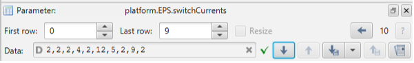
Figure 8 - MCS screenshot of expected platform.EPS.switchCurrents output when GMOD is turned on.
B.11.
To further ensure GMOD is now on/operating,
Getthe parameterpayload.GMOD.FirmwareVersionEnsure that the firmware version of the GMOD image programmed onto the MSP during the pre-launch preparations is returned.
TC Details |
|
MCS Operation |
|
Action/Param Name |
|
Data Expected with TC |
No |
TM Details |
|
Data Expected from TC |
|
Data Size |
Int16 |
Data Info |
Firmware version of the firmware on the GMOD MSP |
Allowed Value(s) |
0000 - FFFF (hex) |
Expected Value(s) |
Firmware version programmed onto the MSP during the pre-launch preparations |
B.12.
To turn off GMOD,
Invokethe actionplatform.EPS.TurnOffGMOD.
TC Details |
|
MCS Operation |
|
Action/Param Name |
|
Data Expected with TC |
No |
TM Details |
|
Data Expected from TC |
No ( + ACK) |
B.13.
To ensure all the PDMs are again off,
Getthe parameterplatform.EPS.actualSwitchStateswithFirst row= 0 andLast row= 9.Ensure that all 0s are returned.
Caution
The FSS is drawing parasitic power so PDM8/Row7 of EPS.actualSwitchStates will always be 1 (ON), even if the state of PDM8/Row7 of EPS.expectedSwitchStates is set to 0 (OFF). In the case of PDM8, the parameter EPS.actualSwitchStates cannot be used to verify the state of PDM8.
Important
PDM3/row2 of the parameter platform.EPS.actualSwitchStates can take up to ~1 minute to return as 0/off following the TurnOffGMOD action.
TC Details |
|
MCS Operation |
|
Action/Param Name |
|
Data Expected with TC |
Yes |
Data Size |
4 bytes, 4 bytes |
Data Info |
|
Allowed Value(s) |
0-9, 0-9 |
Expected Value(s) |
0, 9 |
TM Details |
|
Data Expected from TC |
List of switch states ( + ACK) |
Data Size |
List[0:10] of Booleans |
Data Info |
If 0, a PDM is off. If 1, a PDM is on. |
Allowed Value(s) |
0 or 1 for each switch state |
Expected Value(s) |
0,0,0,0,0,0,0,1,0,0 (PDM 8 on only) - As in Figure 9 below |
Figure 9 - MCS screenshot of platform.EPS.actualSwitchStates output when all PDMs are off.
B.14.
Getthe parameterplatform.EPS.switchVoltageswithFirst row= 0 andLast row= 9.Ensure the voltages are low (i.e. ~0003) confirming that the PDMs are off.
Caution
The FSS is drawing parasitic power so PDM8/Row7 of EPS.switchVoltages is expected to have a value ~250 and not ~0003.
TC Details |
|
MCS Operation |
|
Action/Param Name |
|
Data Expected with TC |
Yes |
Data Size |
4 bytes, 4 bytes |
Data Info |
|
Allowed Value(s) |
0-9, 0-9 |
Expected Value(s) |
0, 9 |
TM Details |
|
Data Expected from TC |
List of switch voltages ( + ACK) |
Data Size |
List[0:10] of Integers |
Data Info |
Voltage measurement for the switches |
Allowed Value(s) |
0000 - FFFF (hex) for each switch voltage |
Expected Value(s) |
PDMs 0-7,9 and 10 ~ 0003, PDM8 ~ 250 - As in Figure 10 below |
Figure 10 - MCS screenshot of expected platform.EPS.switchVoltages output when all PDMs are turned off.
B.15.
Getthe parameterplatform.EPS.switchCurrentswithFirst row= 0 andLast row= 9.Ensure the currents are all low (i.e. ~0003) further confirming that the PDMs are again off.
TC Details |
|
MCS Operation |
|
Action/Param Name |
|
Data Expected with TC |
Yes |
Data Size |
4 bytes, 4 bytes |
Data Info |
|
Allowed Value(s) |
0-9, 0-9 |
Expected Value(s) |
0, 9 |
TM Details |
|
Data Expected from TC |
List of switch currents ( + ACK) |
Data Size |
List[0:10] of Integers |
Data Info |
Current measurement for the switches |
Allowed Value(s) |
0000 - FFFF (hex) for each switch currents |
Expected Value(s) |
~0003 - As in Figure 11 below |
Figure 11 - MCS screenshot of expected platform.EPS.switchCurrents output when all PDMs are turned off.
FSS PDM
B.16.
To assess the health of the FSS PDM, first
Getthe parameterplatform.ADCS.fss1UnfilteredwithFirst row= 0 andLast row= 3 to make sure the FSS is off (i.e. ensure that all zeros (or all F’s) are returned for this parameter).
TC Details |
|
MCS Operation |
|
Action/Param Name |
|
Data Expected with TC |
Yes |
Data Size |
4 bytes, 4 bytes |
Data Info |
|
Allowed Value(s) |
0-3, 0-3 |
Expected Value(s) |
0, 3 |
TM Details |
|
Data Expected from TC |
|
Data Size |
List[0:4] of raw4 |
Data Info |
Unfiltered FSS readings for each cell |
Allowed Value(s) |
00000000 - FFFFFFFF (hex) |
Expected Value(s) |
00000000 or FFFFFFFF for each row |
B.17.
Setthe parameterplatform.EPS.expectedSwitchStateswithFirst row= 7 andLast row= 7 to 1 (PDM on) to turn on the FSS PDM.
TC Details |
|
MCS Operation |
|
Action/Param Name |
|
Data Expected with TC |
Yes |
Data Size |
4 bytes, 4 bytes, boolean |
Data Info |
|
Allowed Value(s) |
0-9, 0-9, 0-1 |
Expected Value(s) |
7, 7, 1 |
TM Details |
|
Data Expected from TC |
No ( + ACK) |
B.18.
Getthe parameterplatform.EPS.expectedSwitchStateswithFirst row= 0 andLast row= 9.Ensure that PDM 8/row 7 is now 1/on.
TC Details |
|
MCS Operation |
|
Action/Param Name |
|
Data Expected with TC |
Yes |
Data Size |
4 bytes, 4 bytes |
Data Info |
|
Allowed Value(s) |
0-9, 0-9 |
Expected Value(s) |
0, 9 |
TM Details |
|
Data Expected from TC |
List of switch states ( + ACK) |
Data Size |
List[0:10] of Booleans |
Data Info |
If 0, a PDM is off. If 1, a PDM is on. |
Allowed Value(s) |
0 or 1 for each switch state |
Expected Value(s) |
0,0,0,0,0,0,0,1,0,0 (only FSS PDM/PDM 8 on) - As in Figure 12 below |
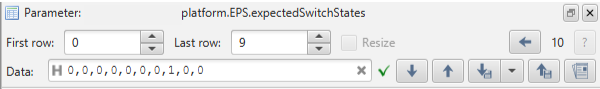
Figure 12 - MCS screenshot of platform.EPS.expectedSwitchStates output when FSS is turned on.
B.19.
Getthe parameterplatform.EPS.switchVoltageswithFirst row= 0 andLast row= 9.Ensure the voltage for the FSS PDM (i.e. PDM 8) is in the range 757 - 773, confirming that this PDM is on.
TC Details |
|
MCS Operation |
|
Action/Param Name |
|
Data Expected with TC |
Yes |
Data Size |
4 bytes, 4 bytes |
Data Info |
|
Allowed Value(s) |
0-9, 0-9 |
Expected Value(s) |
0, 9 |
TM Details |
|
Data Expected from TC |
List of switch voltages ( + ACK) |
Data Size |
List[0:10] of Integers |
Data Info |
Voltage measurement for the switches |
Allowed Value(s) |
0000 - FFFF (hex) for each switch voltage |
Expected Value(s) |
PDM 8 > 250 - As in Figure 13 below |
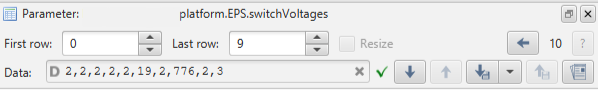
Figure 13 - MCS screenshot of expected platform.EPS.switchVoltages output when FSS is turned on.
B.20.
Getthe parameterplatform.EPS.switchCurrentswithFirst row= 0 andLast row= 9.Ensure the current for the FSS PDM (i.e. PDM 8) is higher than 0003 further confirming that this PDM is on.
TC Details |
|
MCS Operation |
|
Action/Param Name |
|
Data Expected with TC |
Yes |
Data Size |
4 bytes, 4 bytes |
Data Info |
|
Allowed Value(s) |
0-9, 0-9 |
Expected Value(s) |
0, 9 |
TM Details |
|
Data Expected from TC |
List of switch currents ( + ACK) |
Data Size |
List[0:10] of Integers |
Data Info |
Current measurement for the switches |
Allowed Value(s) |
0000 - FFFF (hex) for each switch currents |
Expected Value(s) |
PDM 8 > 0003 - As in Figure 14 below |
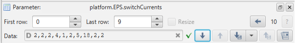
Figure 14 - MCS screenshot of expected platform.EPS.switchCurrents output when FSS is turned on.
B.21.
Getthe parameterplatform.ADCS.fss1UnfilteredwithFirst row= 0 andLast row= 3.Ensure FSS is on (i.e. ensure that non-zero values (or not all Fs) are returned).
TC Details |
|
MCS Operation |
|
Action/Param Name |
|
Data Expected with TC |
Yes |
Data Size |
4 bytes, 4 bytes |
Data Info |
|
Allowed Value(s) |
0-3, 0-3 |
Expected Value(s) |
0, 3 |
TM Details |
|
Data Expected from TC |
|
Data Size |
List[0:4] of raw4 |
Data Info |
Unfiltered FSS readings for each cell |
Allowed Value(s) |
00000000 - FFFFFFFF (hex) |
Expected Value(s) |
>00000000 for each row |
B.22.
To turn off the FSS PDM (i.e. PDM 8),
Setthe parameterplatform.EPS.expectedSwitchStateswithFirst row= 7 andLast row= 7 to 0 (PDM off).
TC Details |
|
MCS Operation |
|
Action/Param Name |
|
Data Expected with TC |
Yes |
Data Size |
4 bytes, 4 bytes, boolean |
Data Info |
|
Allowed Value(s) |
0-9, 0-9, 0-1 |
Expected Value(s) |
7, 7, 0 |
TM Details |
|
Data Expected from TC |
No ( + ACK) |
B.23.
To ensure the set occurred successfully,
Getthe parameterplatform.EPS.expectedSwitchStateswithFirst row= 0 andLast row= 9.Ensure 0s are returned.
TC Details |
|
MCS Operation |
|
Action/Param Name |
|
Data Expected with TC |
Yes |
Data Size |
4 bytes, 4 bytes |
Data Info |
|
Allowed Value(s) |
0-9, 0-9 |
Expected Value(s) |
0, 9 |
TM Details |
|
Data Expected from TC |
List of switch states ( + ACK) |
Data Size |
List[0:10] of Booleans |
Data Info |
If 0, a PDM is off. If 1, a PDM is on. |
Allowed Value(s) |
0 or 1 for each switch state |
Expected Value(s) |
0,0,0,0,0,0,0,0,0,0 (all PDMs off) - As in Figure 15 below |
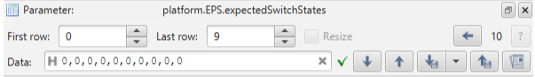
Figure 15 - Screenshot of MCS platform.EPS.expectedSwitchStates outputs when all PDMs are switched off.
B.24.
Getthe parameterplatform.EPS.switchVoltageswithFirst row= 0 andLast row= 9.Ensure the voltages are all low (i.e. ~0003) confirming that all PDMs are again off.
Caution
The FSS is drawing parasitic power so PDM8/Row7 of EPS.switchVoltages is expected to have a value ~250 and not ~0003.
TC Details |
|
MCS Operation |
|
Action/Param Name |
|
Data Expected with TC |
Yes |
Data Size |
4 bytes, 4 bytes |
Data Info |
|
Allowed Value(s) |
0-9, 0-9 |
Expected Value(s) |
0, 9 |
TM Details |
|
Data Expected from TC |
List of switch voltages ( + ACK) |
Data Size |
List[0:10] of Integers |
Data Info |
Voltage measurement for the switches |
Allowed Value(s) |
0000 - FFFF (hex) for each switch voltage |
Expected Value(s) |
PDMs 0-7,9 and 10 ~ 0003, PDM8 ~ 250 - As in Figure 16 below |
Figure 16 - Screenshot of MCS expected platform.EPS.switchVoltages outputs when all PDMs are switched off.
B.25.
Getthe parameterplatform.EPS.switchCurrentswithFirst row= 0 andLast row= 9.Ensure the currents are all low (i.e. ~0003) further confirming that the PDMs are off.
TC Details |
|
MCS Operation |
|
Action/Param Name |
|
Data Expected with TC |
Yes |
Data Size |
4 bytes, 4 bytes |
Data Info |
|
Allowed Value(s) |
0-9, 0-9 |
Expected Value(s) |
0, 9 |
TM Details |
|
Data Expected from TC |
List of switch currents ( + ACK) |
Data Size |
List[0:10] of Integers |
Data Info |
Current measurement for the switches |
Allowed Value(s) |
0000 - FFFF (hex) for each switch currents |
Expected Value(s) |
~0003 - As in Figure 17 below |
Figure 17 - Screenshot of MCS expected platform.EPS.switchCurents outputs when all PDMs are switched off.
B.26.
Again
Getthe parameterplatform.ADCS.fss1Unfilteredto make sure the FSS is off (i.e. ensure that all zeros (or all Fs) are returned for this parameter).
TC Details |
|
MCS Operation |
|
Action/Param Name |
|
Data Expected with TC |
Yes |
Data Size |
4 bytes, 4 bytes |
Data Info |
|
Allowed Value(s) |
0-3, 0-3 |
Expected Value(s) |
0, 3 |
TM Details |
|
Data Expected from TC |
|
Data Size |
List[0:4] of raw4 |
Data Info |
Unfiltered FSS readings for each cell |
Allowed Value(s) |
00000000 - FFFFFFFF (hex) |
Expected Value(s) |
00000000 or FFFFFFFF for each row |
EMOD PDM
B.27.
To turn on EMOD
Invokethe actionplatform.EPS.TurnOnEMOD.
TC Details |
|
MCS Operation |
|
Action/Param Name |
|
Data Expected with TC |
No |
TM Details |
|
Data Expected from TC |
No ( + ACK) |
B.28.
To ensure the EMOD PDM (i.e. PDM 10) is now on,
Getthe parameterplatform.EPS.actualSwitchStateswithFirst row= 0 andLast row= 9.Ensure PDM 10/row 9 = 1/on.
Caution
The FSS is drawing parasitic power on PDM8/Row7 of EPS.actualSwitchStates and so will always be returned as 1 (ON), even if the state of PDM8/Row7 of EPS.expectedSwitchStates is set to 0 (OFF). In the case of PDM8, the parameter EPS.actualSwitchStates cannot be used to verify the state of PDM8.
TC Details |
|
MCS Operation |
|
Action/Param Name |
|
Data Expected with TC |
Yes |
Data Size |
4 bytes, 4 bytes |
Data Info |
|
Allowed Value(s) |
0-9, 0-9 |
Expected Value(s) |
0, 9 |
TM Details |
|
Data Expected from TC |
List of switch states ( + ACK) |
Data Size |
List[0:10] of Booleans |
Data Info |
If 0, a PDM is off. If 1, a PDM is on. |
Allowed Value(s) |
0 or 1 for each switch state |
Expected Value(s) |
0,0,0,0,0,0,0,1,0,1 - As in Figure 18 below |
Figure 18 - MCS screenshot of expected platform.EPS.actualSwitchStates output when EMOD is turned on.
B.29.
Getthe parameterplatform.EPS.switchVoltageswithFirst row= 0 andLast row= 9.Ensure the voltage for the EMOD PDM (i.e. PDM 10/Row 9) is in the range 757 - 773, confirming this PDM is on.
Caution
The FSS is drawing parasitic power so PDM8/Row7 of EPS.switchVoltages is expected to have a value ~250 and not ~0003.
TC Details |
|
MCS Operation |
|
Action/Param Name |
|
Data Expected with TC |
Yes |
Data Size |
4 bytes, 4 bytes |
Data Info |
|
Allowed Value(s) |
0-9, 0-9 |
Expected Value(s) |
0, 9 |
TM Details |
|
Data Expected from TC |
List of switch voltages ( + ACK) |
Data Size |
List[0:10] of Integers |
Data Info |
Voltage measurement for the switches |
Allowed Value(s) |
0000 - FFFF (hex) for each switch voltage |
Expected Value(s) |
PDM 10 > 0003 - As in Figure 19 below |
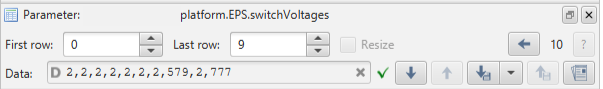
Figure 19 - MCS screenshot of expected platform.EPS.switchVoltages output when EMOD is turned on.
B.30.
Getthe parameterplatform.EPS.switchCurrentswithFirst row= 0 andLast row= 9.Ensure the current for the EMOD PDM (i.e. PDM 10) is higher than in Step B.6. further confirming this PDM is on.
TC Details |
|
MCS Operation |
|
Action/Param Name |
|
Data Expected with TC |
Yes |
Data Size |
4 bytes, 4 bytes |
Data Info |
|
Allowed Value(s) |
0-9, 0-9 |
Expected Value(s) |
0, 9 |
TM Details |
|
Data Expected from TC |
List of switch currents ( + ACK) |
Data Size |
List[0:10] of Integers |
Data Info |
Current measurement for the switches |
Allowed Value(s) |
0000 - FFFF (hex) for each switch currents |
Expected Value(s) |
PDM 10 > 0003 - As in Figure 20 below |
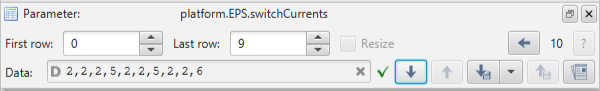
Figure 20 - MCS screenshot of expected platform.EPS.switchCurrents output when EMOD is turned on.
B.31.
To further ensure EMOD is on,
Getthe parameterplatform.ADM.FirmwareVersion.Ensure that the firmware version of the ADM image programmed onto the EMOD MSP during the pre-launch preparations is returned.
TC Details |
|
MCS Operation |
|
Action/Param Name |
|
Data Expected with TC |
No |
TM Details |
|
Data Expected from TC |
|
Data Size |
Int16 |
Data Info |
Firmware version of firmware on the EMOD MSP |
Allowed Value(s) |
0000 - FFFF (hex) |
Expected Value(s) |
Firmware version programmed onto the MSP during the pre-launch preparations |
B.32.
To turn off EMOD
Invokethe actionplatform.EPS.TurnOffEMOD.
TC Details |
|
MCS Operation |
|
Action/Param Name |
|
Data Expected with TC |
No |
TM Details |
|
Data Expected from TC |
No ( + ACK) |
B.33.
To ensure all the PDMs are again off,
Getthe parameterplatform.EPS.actualSwitchStateswithFirst row= 0 andLast row= 9.Ensure that all 0s are returned.
Caution
The FSS is drawing parasitic power so PDM8/Row7 of EPS.actualSwitchStates will always be 1 (ON), even if the state of PDM8/Row7 of EPS.expectedSwitchStates is set to 0 (OFF). In the case of PDM8, the parameter EPS.actualSwitchStates cannot be used to verify the state of PDM8.
TC Details |
|
MCS Operation |
|
Action/Param Name |
|
Data Expected with TC |
Yes |
Data Size |
4 bytes, 4 bytes |
Data Info |
|
Allowed Value(s) |
0-9, 0-9 |
Expected Value(s) |
0, 9 |
TM Details |
|
Data Expected from TC |
List of switch states ( + ACK) |
Data Size |
List[0:10] of Booleans |
Data Info |
If 0, a PDM is off. If 1, a PDM is on. |
Allowed Value(s) |
0 or 1 for each switch state |
Expected Value(s) |
0,0,0,0,0,0,0,1,0,0 (PDM 8 on only) - As in Figure 21 below |
Figure 21 - Screenshot of MCS expected platform.EPS.actualSwitchStates outputs when all PDMs are switched off.
B.34.
Getthe parameterplatform.EPS.switchVoltageswithFirst row= 0 andLast row= 9.Ensure the voltages are all low (i.e. ~0003) confirming that the PDMs are off.
Caution
The FSS is drawing parasitic power so PDM8/Row7 of EPS.switchVoltages is expected to have a value ~250 and not ~0003.
TC Details |
|
MCS Operation |
|
Action/Param Name |
|
Data Expected with TC |
Yes |
Data Size |
4 bytes, 4 bytes |
Data Info |
|
Allowed Value(s) |
0-9, 0-9 |
Expected Value(s) |
0, 9 |
TM Details |
|
Data Expected from TC |
List of switch voltages ( + ACK) |
Data Size |
List[0:10] of Integers |
Data Info |
Voltage measurement for the switches |
Allowed Value(s) |
0000 - FFFF (hex) for each switch voltage |
Expected Value(s) |
PDMs 0-7,9 and 10 ~ 0003, PDM8 ~ 250 - As in Figure 22 below |
Figure 22 - Screenshot of MCS expected platform.EPS.switchVoltages outputs when all PDMs are switched off.
B.35.
Getthe parameterplatform.EPS.switchCurrentswithFirst row= 0 andLast row= 9.Ensure the currents are all low (i.e. ~0003) further confirming that the PDMs are again off.
TC Details |
|
MCS Operation |
|
Action/Param Name |
|
Data Expected with TC |
Yes |
Data Size |
4 bytes, 4 bytes |
Data Info |
|
Allowed Value(s) |
0-9, 0-9 |
Expected Value(s) |
0, 9 |
TC Details |
|
Data Expected from TC |
List of switch currents ( + ACK) |
Data Size |
List[0:10] of Integers |
Data Info |
Current measurement for the switches |
Allowed Value(s) |
0000 - FFFF (hex) for each switch currents |
Expected Value(s) |
~0003 - As in Figure 23 below |
Figure 23 - Screenshot of MCS expected platform.EPS.switchCurents outputs when all PDMs are switched off.
B.36.
The post-launch EPS and battery health checks have now been completed. The Operator should now proceed with one of the sub-procedures listed in EIR-OPS-006: Commissioning that is yet to be completed.
Note
The sub-procedures listed in EIR-OPS-006: Commissioning do not necessarily need to be carried out in the order given. However, procedures ending in ‘Operation’ should only be completed after the relevant ‘Health Check’ procedure for that subsystem has been performed. The ‘EMOD Reprogramming’ procedure must also be performed prior to any EMOD activities. Lastly, ideally, payload operations should be the last item to consider in the commissioning of the spacecraft.
Alternatively, if all sub-procedures listed in EIR-OPS-006: Commissioning have been successfully completed, the Operator may now proceed to EIR-OPS-012: Set Up Nominal Operations .
END OF PROCEDURE