EIR-OPS-004: Initial AOS
Objective
To establish and confirm 2-way communication with EIRSAT-1 for the first time on-orbit.
Introduction
Using this procedure, the Operator will prepare for and make first contact with the spacecraft following launch. At this point in the mission, the flight software is expected to be executing the Separation Sequence. The mission image running on the OBC could be the failsafe or primary1 image. The Operator will communicate with the spacecraft to assess its state and to verify that the antennas are fully deployed prior to making the decision to finish the Separation Sequence. Note that if the failsafe image is the current boot image, this procedure will re-direct the Operator to an alternative procedure to achieve these aims.
Procedure
This procedure contains the following sub-procedures:
Important
Section A should be completed well in advance (hours!) of the first attempted communication pass with EIRSAT-1 to ensure the Operators are prepared for 2-way communication with the satellite. Communication with the spacecraft is required for Sections B and C of this procedure.
Important
This procedure will likely require more than one communication pass. TM/TC should be the Operators sole priority during the passes. Analysis (i.e. Section D) should be performed in parallel by other members of the team or outside of the communication windows.
A. Pre-Pass Preparation
A.1.
Ensure the procedures to be followed in the coming communication pass have been reviewed so that the Operator is familiar with the steps to be taken. More specifically, prior to this pass, the Operator should be familiar with the following:
NACK/Timeout/Unexpected TM (potentially needed if error encountered)
EIR-OPS-005: Failsafe at Initial AOS (potentially needed if error encountered)
A.2.
To use the pass time efficiently, prepare the parameters and actions (i.e. open them in MCS) that will be used during the pass, as demonstrated in Figure 1.
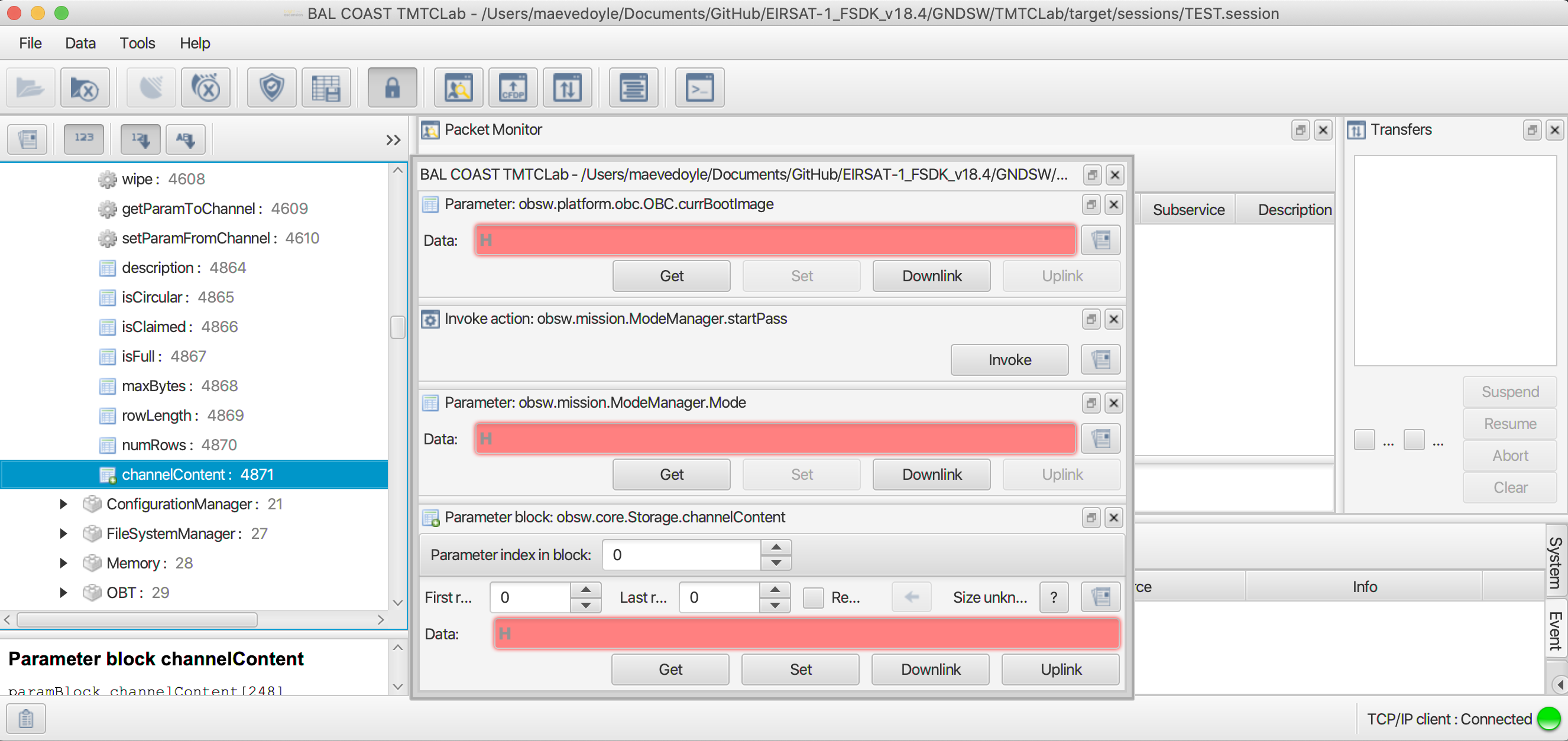
Figure 1 - Actions and parameters opened in MCS prior to the Start Communication Pass Procedure.
A.3.
Taking the time since on-orbit deployment (i.e. the time since power ON) and given the known frequency at which the different data packets are logged on-board, approximate the number of rows of data that will be available for downlink in the ADM, HK, TED, PASCAL, etc. storage channels by the first communication pass with EIRSAT-1.
Use ROW to assist with this.
A.4.
In Section C of this procedure, EIRSAT-1’s first Large Data Transfer (LDT) of logged on-board data will be set up. In preparation for this, ensure that you:
Read the 3. Prerequisite Knowledge ❗ Section in Real-time Operations introduction section of this manual,
Read and set up the actions/parameters for the EIR-OPS-011: Downlink Data From Storage procedure, and
Are familiar with how to use ROW .
A.5.
Determine the durations of the next communication passes with the satellite and when they will occur.
A.6.
Using the upcoming pass durations (determined in Step A.5) and the expected data available for downlink (determined in Step A.3), estimate the amount of data to downlink from the HK, Event and ADM (and/or other) storage channels during the first communication passes with EIRSAT-1.
Use ROW to assist with this.
Suggested downlink priorities can be found in Section C of this procedure and, for the case where failsafe is the current boot image at initial AOS, Section A of the EIR-OPS-005: Failsafe at Initial AOS procedure.
B. Initial Get TCs
Important
This section should only be attempted more than 45 minutes after on-orbit deployment (i.e. after antenna deployment) and when the spacecraft is expected in the FoV of EIRSAT-1’s GS.
B.1.
GettheVersion.satelliteStringparameter frequently (i.e. with ~10 seconds between each TC).Begin sending these TCs ~30 seconds before the expected time of AOS.
Continue to send these TCs until:
TM is received from EIRSAT-1 (as per the TM/TC Details table),
The expected time of LOS has passed, or
An issue is expected with the communications chain. Refer to EIR-OPS-032: Separation Sequence Restarted for some guidance in this case and request support from senior team members!
TC Details |
|
MCS Operation |
|
Action/Param Name |
|
Data Expected with TC |
No |
TM Details |
|
Data Expected from TC |
|
Data Size |
8 bytes |
Data Info |
the “EIRSAT-1” string. |
Allowed Value(s) |
|
Expected Value(s) |
|
B.2.
If no TM or a NACK is returned from the spacecraft over the pass duration, do not proceed with the remainder of this procedure. Instead, proceed to NACK/Timeout/Unexpected TM and discuss the situation with the senior team.
Else, if the
satelliteStringparameter is returned (as shown in Figure 2), continue with the remainder of this procedure.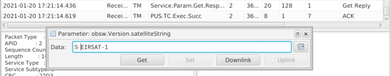
Figure 2 - TM from the
satelliteStringparameter in string format.
B.3.
Gettheplatform.OBC.obc.currBootImageparameter to determine the OBC’s current boot image.Take note of this value for use in later steps.
TC Details |
|
MCS Operation |
|
Action/Param Name |
|
Data Expected with TC |
No |
TM Details |
|
Data Expected from TC |
|
Data Size |
1 byte |
Data Info |
the current boot image of EIRSAT-1 |
Allowed Value(s) |
00, 01 and 02 (Hex) |
Expected Value |
00 or 01 (Hex) |
Where…
|
Image |
|---|---|
0 |
failsafe |
1 |
primary1 |
Note
The spacecraft’s first boot image should be the primary1 image. If the spacecraft reboots (or the OBC resets) <2 hours after booting, the primary1 image will be marked as unstable and the failsafe image will be entered.
B.4.
Based on the
currBootImage:Ensure the appropriate SCDB is loaded into MCS, and
Determine what step to proceed to next using the below table.
|
Next step |
|---|---|
0 |
Skip to Step B.7. As there is no ModeManager in failsafe and so ModeManager-related steps should be skipped. |
1 |
Proceed to Step B.5. |
B.5.
Invokethemission.ModeManager.startPassaction to start a communication pass.
Note
Enabling a communication pass will enable automatic and periodic transmission of live HK data from the spacecraft in place of the TM beacon data, which is transmitted outside of the pass. Automatic transmission of any on-board events raised during the pass will also be enabled throughout the pass. This on-board behavior will automatically time-out ~3 minutes after the last TC is received by the spacecraft.
TC Details |
|
MCS Operation |
|
Action/Param Name |
|
Data Expected with TC |
No |
TM Details |
|
Data Expected from TC |
No ( + ACK ) |
B.6.
Getthemission.ModeManager.Modeparameter.Confirm that the Separation Sequence Mode (i.e. 0) is returned.
TC Details |
|
MCS Operation |
|
Action/Param Name |
|
Data Expected with TC |
No |
TM Details |
|
Data Expected from TC |
|
Data Size |
1 byte |
Data Info |
the current Operational Mode of EIRSAT-1 |
Allowed Value(s) |
00- 04 (Hex) |
Expected Value(s) |
00 (Hex) |
Where…
|
Operational Mode |
|---|---|
00 |
Separation Sequence |
01 |
Commissioning |
02 |
Nominal |
03 |
WBC |
04 |
Safe |
Tip
The next steps of this procedure primarily instruct the Operators to Get parameters, with no instruction on what to do about the returned TM. This is because this information will be used in later steps of this procedure and/or to assist the data analyses of other procedures.
B.7.
To determine which state the Separation Sequence is in and to confirm that resistor burn attempts are still on-going,
Getthemission.SeparationSequence.stateparameter.Ensure that the returned state is between 02 - 09.
TC Details |
|
MCS Operation |
|
Action/Param Name |
|
Data Expected with TC |
No |
TM Details |
|
Data Expected from TC |
|
Data Size |
1 byte; 11 bytes |
Data Info |
the current state of the Separation Sequence |
Allowed Value(s) |
00 - 09 or 42 (Hex) |
Expected Value(s) |
02 - 09 (Hex) |
where…
|
State |
|---|---|
00 |
Init |
01 |
PostLaunchWait |
02 |
MinYPrimaryBurnStart |
03 |
PlusYPrimaryBurnStart |
04 |
MinXPrimaryBurnStart |
05 |
PlusXPrimaryBurnStart |
06 |
BurnTimeWait |
07 |
BurnOff |
08 |
BetweenBurnWait |
09 |
SecondaryBurnStart |
42 |
Finish |
B.8.
Gettheplatform.ADM.SwitchesStatusesparameter to very preliminarily confirm the current state of the ADM switches.
Note
The state of the ADM switches determined in this step will be confirmed later with downlinked data.
TC Details |
|
MCS Operation |
|
Action/Param Name |
|
Data Expected with TC |
No |
TM Details |
|
Data Expected from TC |
|
Data Size |
1 byte |
Data Info |
a 4-bit bitmap of the ADM switch states + 1 error bit |
Allowed Value(s) |
00000 - 11111 (binary) |
Expected Value |
01111 (No error, all ADM switches open) |
Where…
|
ADM Switch States |
|---|---|
0 |
Closed |
1 |
Open |
and…
Bits |
Antenna element |
|---|---|
Bit 0/LSB |
+X |
Bit 1 |
+Y |
Bit 2 |
-X |
Bit 3 |
-Y |
Bit 4/MSP |
N/A (error bit, where 1 = error) |
B.9.
Getthecore.OBT.uptimeparameter to determine the elapsed time since the last reboot.
TC Details |
|
MCS Operation |
|
Action/Param Name |
|
Data Expected with TC |
No |
TM Details |
|
Data Expected from TC |
|
Data Size |
4 bytes |
Data Info |
Uptime (i.e. elapsed time since the last reboot) |
Allowed Value(s) |
00000000 - FFFFFFFF (hex) |
Expected Value(s) |
> 0 |
B.10.
Getthecore.OBT.timeparameter 10 times, with ~5 seconds between each TC, to determine what on-board time corresponds to in real time.
Note
This data will be used by the GS team after the pass. The Operator does not need to perform any assessment of the returned TM during the pass.
TC Details |
|
MCS Operation |
|
Action/Param Name |
|
Data Expected with TC |
No |
TM Details |
|
Data Expected from TC |
|
Data Size |
4 bytes |
Data Info |
EIRSAT-1’s on-board time |
Allowed Value(s) |
00000000-FFFFFFFF |
Expected Value(s) |
>0 |
B.11.
Gettheplatform.EPS.busVoltagesparameter withFirst row=Last row= 0 to determine the on-board voltage levels.
Danger
If busVoltages[0] <780 (dec), which corresponds to ~7.0V, the Operators are advised to postpone initiating any procedures in this pass in which the spacecraft consumes more power. This includes procedures that lead to increased RF transmissions, powering ON/enabling experiments and operating the ADCS. In the case where data downlinking is required for failure analyses, a limited amount of data downlinking is permitted.
TC Details |
|
MCS Operation |
|
Action/Param Name |
|
Data Expected with TC |
|
Data Size |
2 bytes, 2 bytes |
Data Info |
The first and last rows/indexes of the parameter to get |
Allowed Value(s) |
0 - 3 |
Expected Value(s) |
0, 0 |
TM Details |
|
Data Expected from TC |
|
Data Size |
Int10 |
Data Info |
|
Allowed Value(s) |
0 - 1023 (dec) |
B.12.
Gettheplatform.CMC.tempaturePaparameter to determine the CMC PA temperature.
Danger
If temperaturePa >50 degrees Celsius, the Operators are advised to postpone initiating any procedures in this pass in which a significant amount of RF transmissions are likely. In this case, the Operators should monitor temperaturePa and only initiate such procedures when the parameter value falls below 45 degrees Celsius.
TC Details |
|
MCS Operation |
|
Action/Param Name |
|
Data Expected with TC |
No |
TM Details |
|
Data Expected from TC |
|
Data Size |
signed Int8 |
Data Info |
Temperature of the CMC power amplifier in degrees C |
Allowed Value(s) |
-128 - 128 (dec) |
B.13.
The Operators should now proceed with LDTs, following the EIR-OPS-011: Downlink Data From Storage procedure. However, this should be done with care for the current state of the spacecraft (i.e. as the ‘Danger’ boxes advise in the previous two steps).
Important
LDTs should only be requested one at a time! When a transfer is complete, another can be started using the EIR-OPS-011: Downlink Data From Storage procedure. Get / Set TCs of other procedures may be carried out in parallel to LDTs, however, it should be noted that in this case the TM response time will be slowed.
For guidance on what to downlink:
If
currBootImage= 1 in Step B.3, proceed to Section C of this procedure.Else, if
currBootImage= 0 in Step B.3, proceed to the EIR-OPS-005: Failsafe at Initial AOS procedure.
Danger
If in the failsafe image, live transmission of event data is not enabled as part of this procedure, and so the Operator should be careful to monitor the CMC PA temperature (i.e.
platform.CMC.temperaturePa) when downlinking data during the pass.
C. Data Downlink
C.1.
For the remainder of the pass, downlink data from on-board storage according to the EIR-OPS-011: Downlink Data From Storage procedure.
Warning
Section B of EIR-OPS-011: Downlink Data From Storage (i.e. Tx Convolutional Encoding Management) SHOULD NOT BE FOLLOWED during the initial passes of the mission, until the GS team confirm that 2-way communications is sufficiently stable.
For the first pass of initial AOS, it is recommended that the Operator downlink data according to the priorities listed in the table below.
For all subsequent passes, some NEW rows of
EventandHKdata should always take priority to assess the current state of the spacecraft. Only then should the priorities in the table be re-assumed.
Note
In this table the Operator is advised to downlink ‘some’ rows of a particular data type and whether the OLDest or NEWest rows of data in storage should be given preference. This is done with the assumption that the time constraint of the communication pass will not allow the Operator to get all the desired data downlinked in a single pass.
Priority |
What Data? |
Why? |
|---|---|---|
Highest |
Some NEW rows of |
to determine the current state of the spacecraft |
Some OLD rows of |
to assess the progress of the Separation Sequence following first boot |
|
Some OLD rows (at least ~hours worth) of |
to assess if antenna deployment occurred during the first burn attempts |
|
Some NEWer rows of |
to learn more about the state of the spacecraft following boot |
|
Lowest |
Some OLDer rows of |
C.2.
If a communication pass is over proceed to Section D, however, for later passes and while antenna deployment is still being confirmed, the Operator should return to this section and continue to downlink data from the above table as well as any additional data desired as a result of the analysis carried out in Section D.
D. Data Analysis (After the Communication Pass)
Note
The analysis to be carried out by the team is very dependent on the findings as well as what data was successfully downlinked in Section C. Therefore, rather than a strict set of instructions, this section instead provides information to help guide the Operator in their analyses. Also note that in addition to any data downlinked by the UCD GS, data obtained via the amateur radio community may also be used to support the analysis/findings.
SPACECRAFT HEALTH CHECK
D.1.
Any HK data downlinked should now be checked to assess the current state of the spacecraft and its subsystems.
Do any of the HK parameters cause reason for concern? e.g:
Is the most recent value of the Uptime parameter consistent with the expected Mission Elapsed Time (MET) since launch?
Are the battery bus voltage levels nominal?
Are the various EPS and/or battery reset counters as expected given their pre-launch values?
Has the temperature of the CMC Power Amplifier stayed within expected/acceptable limits since RF transmissions were enabled?
Tip
In addition to the most recent value of each parameter, check how the values changed with time. Use the Grafana to help with this.
2-WAY COMMUNICATION CONFIRMATION
D.2.
The downlinked data should now be assessed to confirm with confidence, that:
full antenna deployment has occurred, and
nominal 2-way communication have been achieved.
To do this, the following should be considered:
Does the downlinked Event data suggest that the Separation Sequence successfully progressed to and through the different burn and between-burn-wait states (i.e. are Separation Sequence ‘StateFunctionComplete’ events observed with Event Data = the IDs of the burn and between-burn-wait states)?
Tip
To aid this assessment, the Operators can review Event log data downlinked during the MMTs here for comparison with their data.
In the downlinked ADM data:
Do the ADM switch states, read by both the OBC and the EMOD MSP (i.e.
mission.SeparationSequence.AntSwitchesStatusesandplatform.ADM.SwitchesStatuses), indicate that the antenna elements have been deployed?Do the deployment times of the different elements coincide with the resistor burns?
Do the PDM currents show that the correct current went through the resistors for the correct amount of time during the resistor burns?
In the downlinked HK data:
Check that the temperature of the CMC Power Amplifier increased only after RF transmissions were enabled to confirm that RF transmissions enabled when expected.
D.4.
While antenna deployment is not confirmed, continue to downlink data (i.e. as in Section C) during subsequent passes until the data indicates with confidence that all antennas have deployed.
However, once the successful deployment of the antennas is confirmed, the Operators can begin the EIR-OPS-006: Commissioning Procedure.
END OF PROCEDURE