Real-Time Operations
Important
Operators MUST read the below sections prior to operating EIRSAT-1 to understand their interface to the spacecraft, the layout of the operational procedures and the format of the possible response that could be received from the spacecraft.
The sections below, with brief descriptions of their contents, are as follows:
1. The MCS GUI : this section presents the layout and contents of the MCS GUI that an Operator uses to communicate with the spacecraft.
2. Spacecraft Database : this section demonstrates how to navigate through the spacecraft database (SCDB) and describes, with examples, the actions and parameters that can be accessed via the MCS interface.
3. Prerequisite Knowledge ❗ : this section presents all the information required to perform operations and that must be understood in full before performing an operation. Many of these subsections may be required repeatedly and are briefly described:
3.1 Spacecraft Telemetry - Different TM types that can be received from spacecraft
3.2 Large Data Transfers - The method and rules of downlinking large quantities of data
3.3 On-Board Storage - Determine from which memory type the data should be downlinked
3.4 Storage Channels & Downlink Logic - Describes different types of storage channels and how to calculate what rows of data should be downlinked
3.5 EIR_OPS Procedure Example - Description and example of the format of an Operational Procedure
4. Operator Tips : this section provides additional non-critical information/tips for Operators that may be useful to know when working with MCS, its Layouts feature and the operational procedures.
5. EIR_OPS : this section lists of the EIRSAT-1 Operational Procedures.
1. The MCS GUI
The MCS GUI is the Operator’s interface to the spacecraft during operations. The sections below describe the purpose of and how to open the different components of the Operator’s interface and the format of the real-time Operational Procedures.
MCS is a GUI that allows you to communicate with the spacecraft. Its purpose is to allow efficient interaction with the on-board software (OBSW) via parameters and actions. MCS works by loading a ‘Spacecraft Database’ (SCDB - described below) generated by the FSDK tooling to communicate with the spacecraft.
A toolbar is located at the top of the MCS window. The icon in the red box in Figure 1, when clicked, opens the ‘Packet Monitor’ (described below). A ‘Transfer Window’ should also be opened in MCS (purple box).

Figure 1 - Location of Packet Monitor and Transfer Window buttons
In Figure 2, the blue box surrounds the ‘Mission Explorer’ window, the red box surrounds the Packet Monitor, the purple box surrounds the ‘Transfer Window’ and the green box shows the ‘System/Debug/Event Console’, all of which are described below.
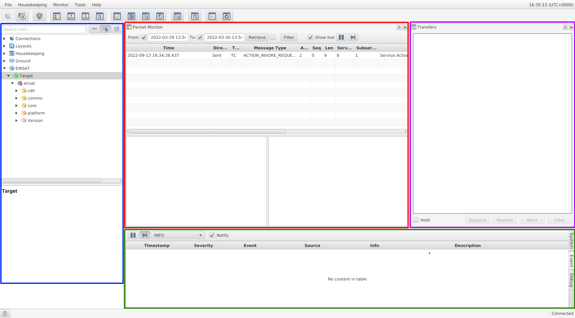
Figure 2 - MCS with different sections highlighted.
1.1 Packet Monitor
The packet monitor provides a log of packets exchanged between the ground and the on-board software. The different columns described in Table 1 contain decoded information relating to the packet.
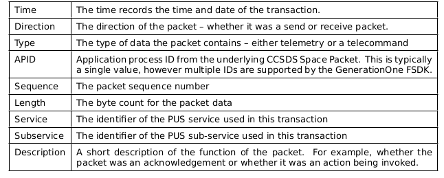
Table 1 - Packet Monitor Log Columns
1.2 Mission Explorer
The Mission Explorer displays various aspects of the mission in a tree structure including the currently open SCDB which will be described in more detail in Section 2. With the SCDB as an input, the Mission Explorer provides a collapsible/expandable tree view of all the component groups and component instances present in the deployment/image.
1.3 System/Debug/Event Console
The System/Debug/Event console provides three tabbed windows.
System - The system tab gives an overview of the actions being taken by MCS.
Event - The event tab allows a more human readable form (not packets) to view raised events.
Debug - The debug tab can provide structured output from the standard output stream.
Note
Of these three tabs, the Event tab provides the most useful information to the Operator.
1.4 Transfers Window
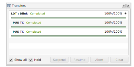
Figure 3 - Transfer Window
MCS’s transfer window is shown in Figure 3. When data is downlinked/uplinked the transfer will be added to the transfer list/window, detailing the current state of the transfer (e.g. the percentage complete).
2. Spacecraft Database
The Spacecraft Database (SCDB) describes all of the actions, parameters, exceptions and events for the spacecraft, including their numeric IDs. The MCS will be configured with an asset (satellite), target (ops station computer) and a SCDB deployment. To load a SCDB into the MCS GUI, click File → Manage Mission, the window shown in Figure 4 will open where MiniFlatSat is the Asset and MiniFlatSat_Prim1 is the Target. A primary and failsafe SCDB will be available. To update either of these deployments, select the desired SCDB and click Update Deployment button. This will bring up a new window where you can give the deployment an id and point the Definition file parameter towards your SCDB file. To switch to a different SCDB, select the desired SCDB and click Switch Deployment. The deployed SCDB will be open in the Mission Explorer window. The Mission Explorer tree view provides a list of all the component groups and component instances present in the deployment. The SCDB in Figure 4 is called ‘Primary 1’.
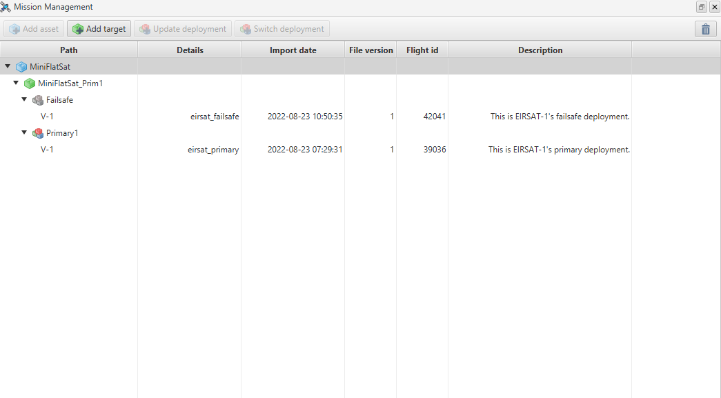
Figure 4 - Manage Mission window of MCS showing possible SCDBs, primary and failsafe that can be loaded into the Mission Explorer
Figure 5 shows the Primary 1 SCDB in the Mission explorer window. Clicking the arrow beside the SCDB opens the first layer of component groups i.e. cdh, comms, core, platform, payload and mission. Component groups consist of sub-groups and individual components with associated actions and parameters (e.g. all components responsible for data handling exist in the cdh group). Components then consist of actions and parameters (described below).
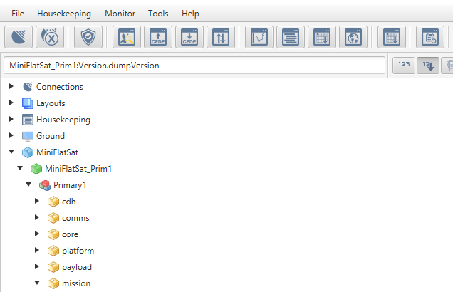
Figure 5 - First layer of component groups of Primary 1 SCDB
To further describe the SCDB interface, the path mission.ModeManager.transitionToSafeMode is taken as an example. In Figure 6, the mission component is expanded and then the Mode Manager is expanded. The Action TransitionToSafeMode is observed in the blue box and the parameter Mode is in the green box. See subsections 2.1 and 2.2 for more information on Actions and Parameters in the SCDB.
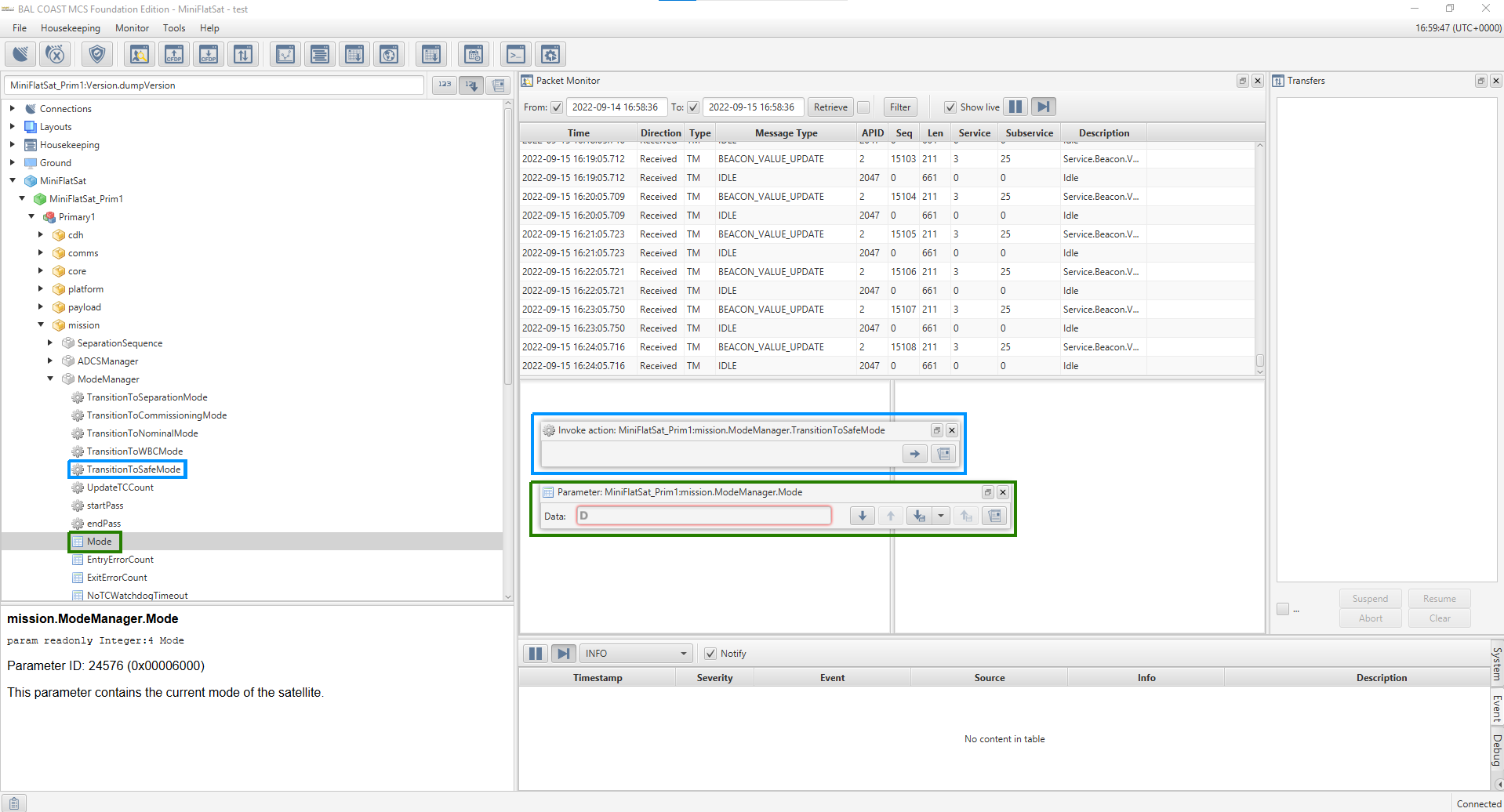
Figure 6 - Expanded mission component in SCDB
2.1 Actions
An action is a function that the component can be commanded to perform. This is known as ‘invoking’ the action. An action is represented with a cog symbol in the SCDB as shown in Figure 6.
Figure 7 is an example of an action. In this example, the Mission Explorer window was used to navigate through the SCDB to mission.ModeManager.transitionToNominalMode . By clicking on the action transitionToNominalMode , the Invoke options appears, right pointing arrow button as shown in the blue box. A description of the action and the numeric ID is also displayed in the lower left hand corner as shown in the red box.
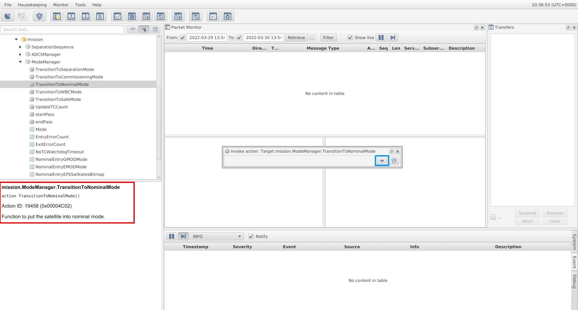
Figure 7 - Action transitionToNominalMode without a parameter
Actions can also take input data as ‘action arguments’.
Note
An action argument is an input parameter that is required to invoke the action.
As an example of this, in Figure 8, the Mission Explorer window was used to navigate through the SCDB to core.Storage.wipe . By clicking on the action wipe , the Invoke option appears, as shown in the blue box. However, there is now also an action argument ChannelID option that must be filled in before invoking the action. A description of the action and the action argument to be entered is displayed in the lower left hand corner as shown in the red box.
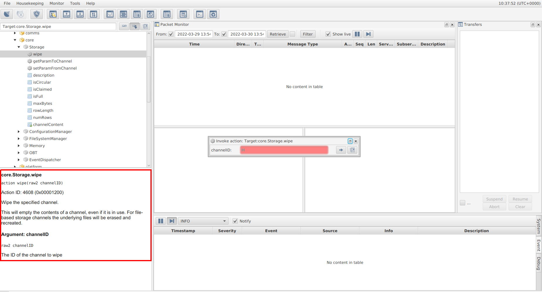
Figure 8 - Action wipe with a parameter
Note
For every action argument and parameter the type of data and size will be included. For example, in Figure 10, the parameter rwMode is a boolean. The allowed values are therefore 0 and 1. Another common data type is an integer - the size of the integer is given in decimal in the SCDB but the values input into MCS are in hex and will be returned in hex. For an 8 bit integer, as in Figure 10, 2 hex values are expected. 1 hex value = 4 bit integer.
2.2 Parameters
Parameters represent data associated with a component. There are different operations associated with parameters. Some parameters are read-only; these often represent some on-board measurement. Other parameters are read-write and are used to modify the configuration of a component.
The possible parameter operations are:
Get - Click down arrow button (blue box in Fig. 9) to read the current value of a parameter
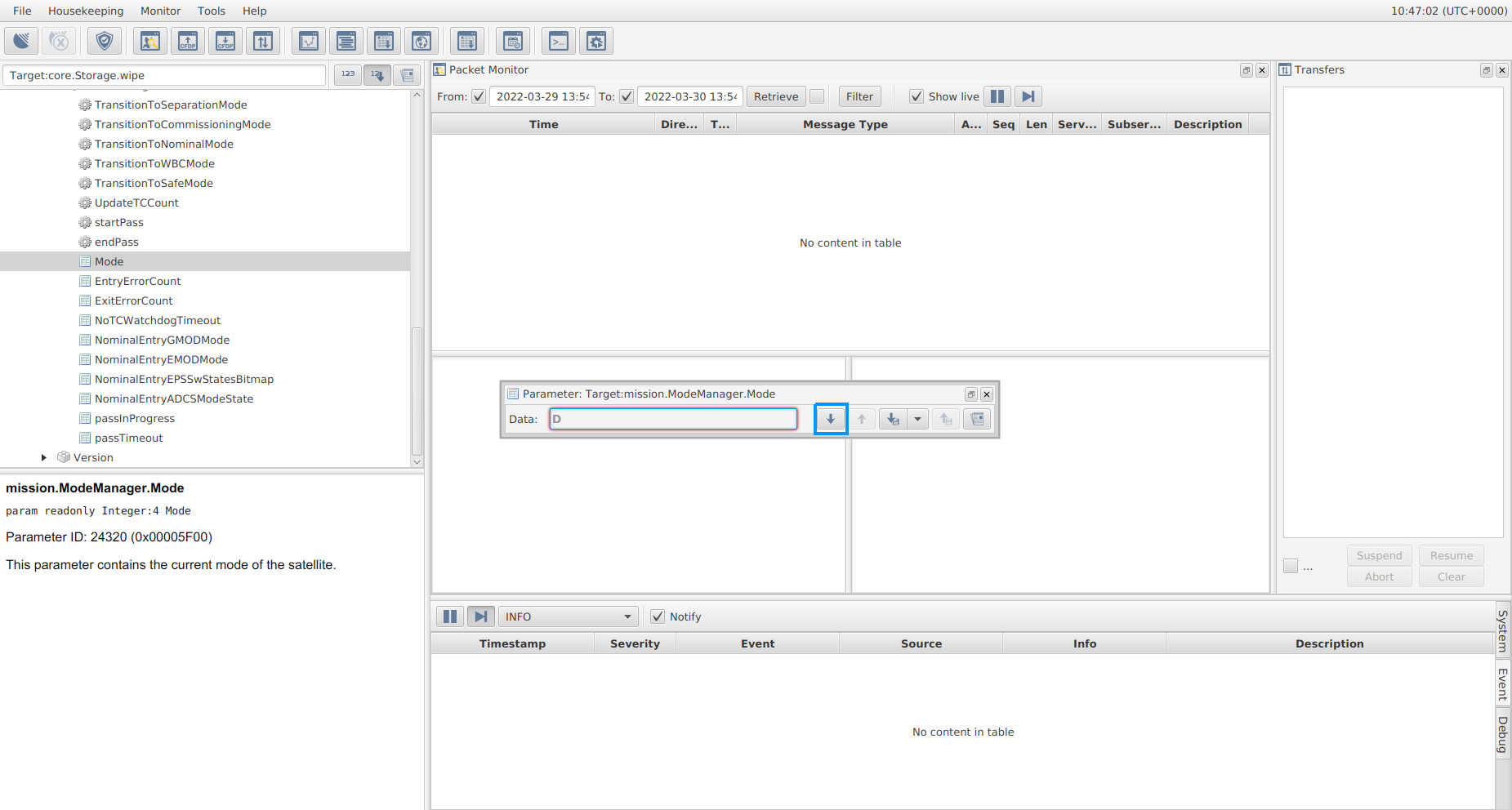
Figure 9 - By following the path mission.ModeManager.Mode , the read-only Mode parameter can be gotten
Set - Click the up arrow button (green box in Fig. 19) change the current value of a parameter
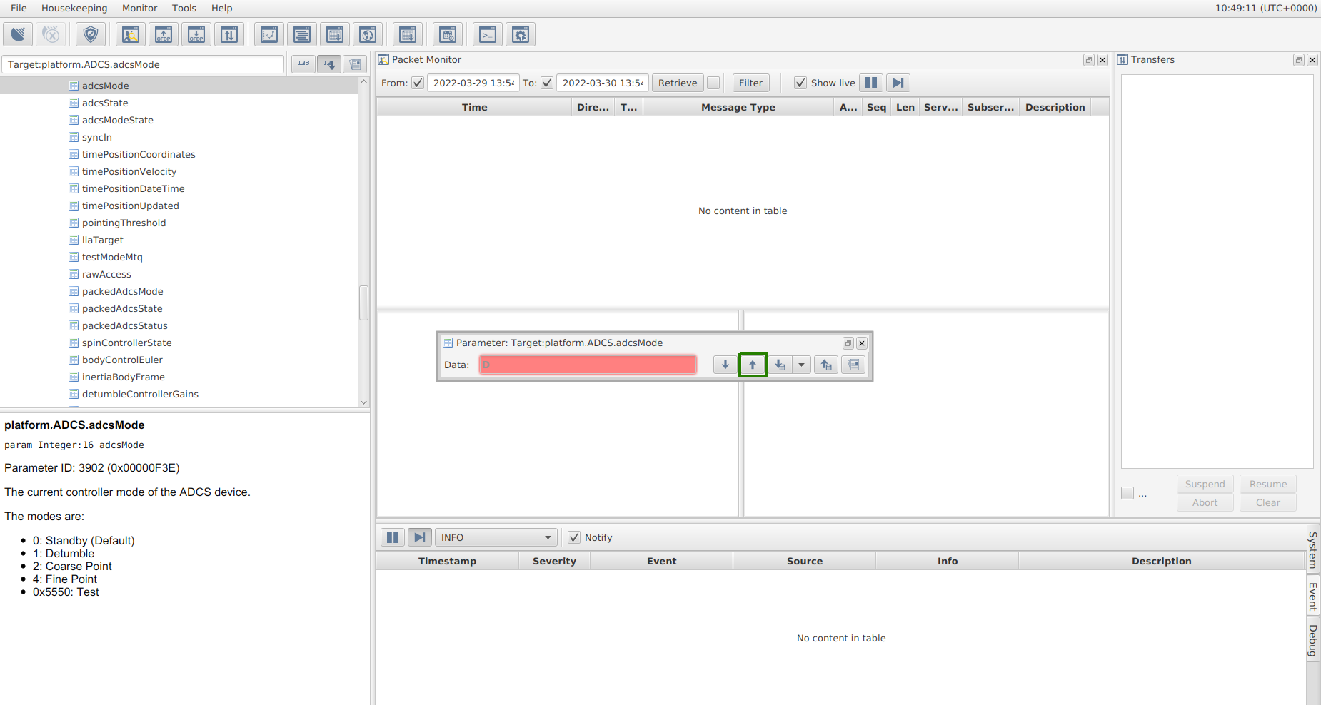
Figure 10 - By following the path platform.ADCS.adcsMode , the read and write adcsMode parameter can be set or gotten
Get (and set) telecommands are limited to a single packet (i.e. small transactions). For large data transfers, parameters will need to be downlinked (and uplinked).
Downlink - similar to the ‘get’ operation but for a large set of data. Once this command is clicked (down arrow button with adjacent file icon in blue box in Fig. 11), a window pops up prompting the Operator to name a file to downlink the data to. This command will allow up to 16384 bytes of data to be retrieved in a single transfer.
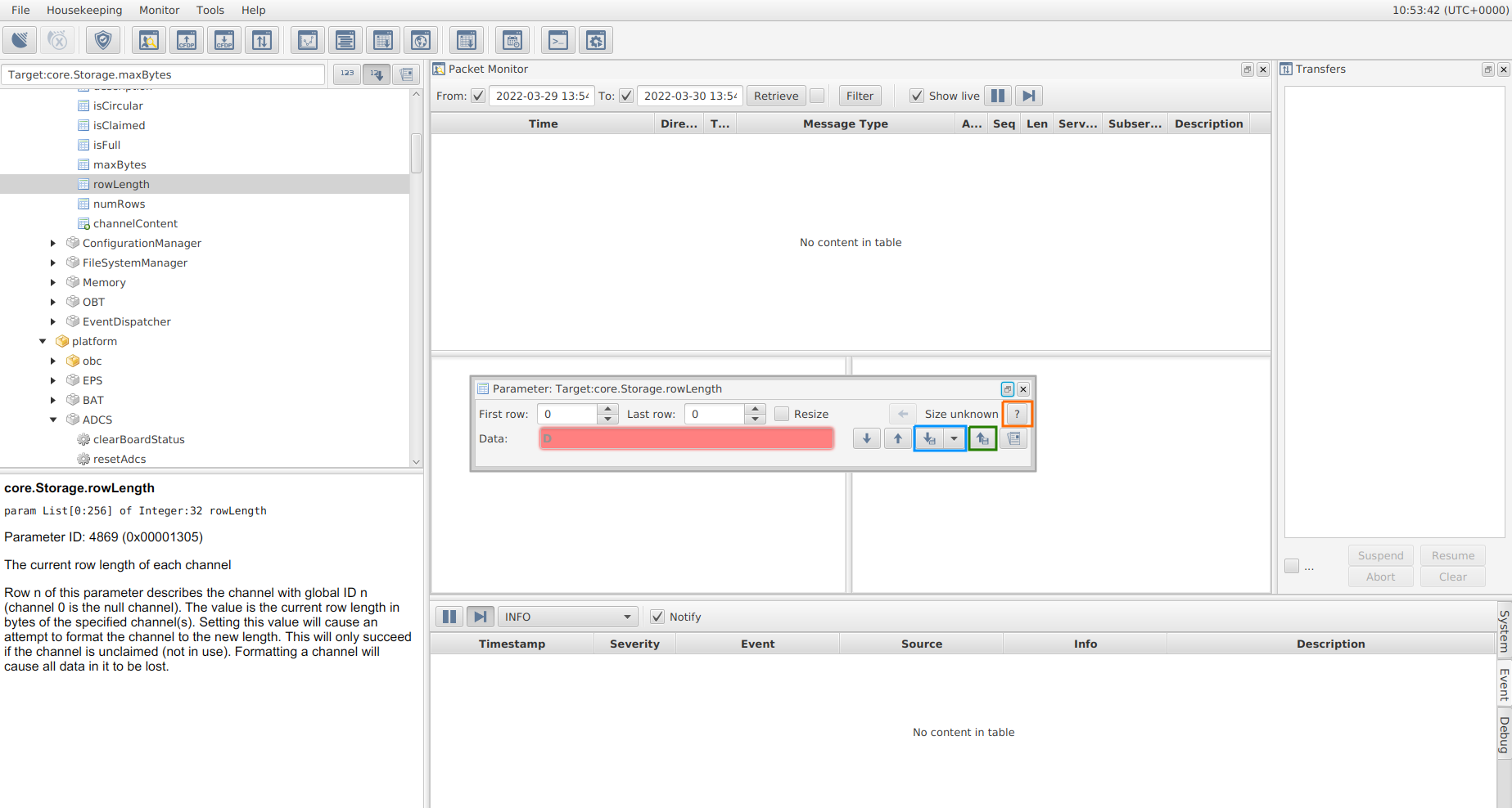
Figure 11 - By following the path core.Storage.rowLength , the rowLength parameter can be gotten, the current size of the parameter can also be queried (green box).
Uplink - It acts in a similar manner to a ‘set’, but uses an Operator-provided data file to allow for more data to be sent to set the parameter. The file should be the same size as the parameter (or parameters, where there is a row range) being set. Once this command is clicked (up arrow button with adjacent file icon in green box in Fig. 11), a window pops up prompting you to select the file to uplink the data from.
Query - query a parameter to find out the current size of either it’s rows or byte count, depending on the parameter type. It is shown as a
?in MCS, as highlighted by the orange box in Figure 11.
As with actions, each parameter has a unique numeric ID which is used to identify it in the on-board software.
In addition to standard single-valued parameters, it is also possible to have multi-row parameters or parameter arrays, as shown in Figure 12. In this case, the parameter is defined as a List[0:512] of Integer 32, so this parameter array has up to 512 values, each of which are 4 bytes.
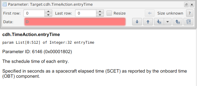
Figure 12 - Example of parameter array
3. Prerequisite Knowledge ❗
Important
Ensure that the information provided in this section is read and understood in full prior to operations being performed.
3.1 Spacecraft Telemetry
During a communications pass, a number of different TM types are expected from the spacecraft. The most obvious TM type is the TM that contains the data requested via TC. In addition to this requested data, the spacecraft will also send an (non-)acknowledgment packet to indicate the (non-)successful execution of the action instructed by the TC. These ‘ACK’ and ‘NACK’ packets are described in sections 3.1.1 and 3.1.2, respectively. Section 3.1.3 discusses the scenario when no response is received from the spacecraft (i.e. a ‘Timeout’) when a response is expected. Section 3.1.4 mentions additional TM types that may be observed during a communication pass - HK TM, which is automatically and periodically transmitted throughout the pass, and live event data.
3.1.1 ACKs
In addition to TM/data specifically requested from the spacecraft (e.g. via a Get command), the spacecraft will respond to every TC with an acknowledgment (‘ACK’) TM packet. In MCS, an ACK TM packet appears in the Packet Monitor window as shown in Figure 13. A green tick will also appear in the parameter box, as highlighted by the red box in Figure 13.
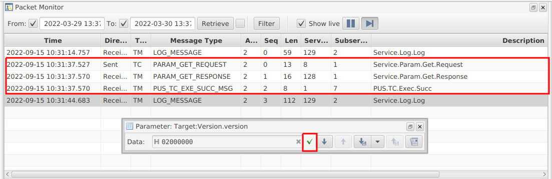
Figure 13 - Example of TC with ACK TM responses in the Packet Monitor
An ACK signifies that the TC was executed successfully on-board the spacecraft. The Operator should keep watch of the Packet Monitor following each TC for the accompanying ACK TM to ensure that the TC was a success.
3.1.2 NACKs
If the action associated with a TC is not carried out successfully on-board the spacecraft, a negative acknowledgment (‘NACK’) is received in response to a TC instead of an ACK. A NACK commonly indicates that there was an issue with the data in the TC. As examples, NACK TM will be observed in response to:
A TC that requests to access the
First rowandLast rowof a parameter, whereLast rowexceed the number of rows in the parameterA TC that requests to access the
First rowandLast rowof a parameter, whereFirst row>Last rowA TC that attempts to set a parameter to an invalid value, where the value is considered ‘invalid’ due to it being the incorrect size or due to logic implemented in the software
In MCS, a NACK TM packet appears in the Packet Monitor window and as a red x beside the parameter/action. In Figure 14, the NACK in the packet monitor and the red x are highlighted in blue boxes because the operator attempted to downlink an incorrect number of rows.
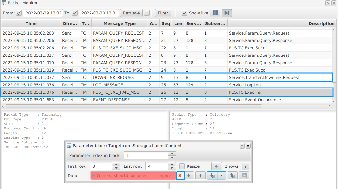
Figure 14 - An example of a TC with a NACK TM response in the Packet Monitor
Note that, NACKs are commonly accompanied by a live event (see Section 3.4) as an event is raised to also log the error on-board. The Operator should keep watch of the Packet Monitor following each TC to ensure that a NACK is not returned. If a NACK is returned by the spacecraft, the Operator should pause any on-going procedures and contact the Software and/or Systems Engineer to assess the plan of action (POA). However, if time remains in the pass and the NACK was not associated with the standard EIR-OPS-011: Downlink Data From Storage procedure, the Operator should continue to downlink (HK, TED, event, etc.) data from storage for later analysis.
3.1.3 Timeouts
MCS is configured to always expect either an ACK or NACK in response to a TC. When neither is received (i.e. when the spacecraft does not respond), a grey “x” will appear beside the parameter and when hovered over, the ‘Activity Timed Out’ banner shown in Figure 15 appears in the MCS GUI. If a timeout occurs, the Operator should pause any on-going procedures and contact the Software and/or Systems Engineer to assess the POA. However, if time remains in the pass and the timeout was not associated with the standard EIR-OPS-011: Downlink Data From Storage procedure, the Operator should continue to downlink (HK, TED, event, etc.) data from storage for later analysis.
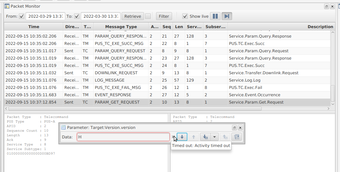
Figure 15 - An example of a TC with no response (i.e. no ACK/NACK) in MCS
Warning
In the bottom left-hand corner of MCS, the error message shown Figure 16 will be observed when a timeout occurs. This error message persists even after a successful TC. As this can lead to confusion over which TC timed-out, it is advised that the Operator click the button to the left of the error message and select the ‘Clear All’ option after every timeout.

Figure 16 - An example of the error message that appears in MCS following a timeout
3.1.4 Live Events/HK Data
In addition to the TM described above, live HK and event data can also populate the Packet Monitor during a communication pass. Further information on the each event received will appear in the Event tab of the System/Event/Debug console. While the Operator should be aware of these live data packets, the Operator should not react to the information rashly. If a live event is observed that is of concern, the Operator should pause any on-going procedures and contact the Software and/or Systems Engineer to assess the POA. However, if time remains in the pass, the Operator should continue to downlink (HK, TED, event, etc.) data from storage for later analysis.
3.2 Large Data Transfers
Large quantities of data requested for downlink by the GS will be separated out over multiple Large Data Transfer (LDT) ‘parts’. The different parts will be downlinked in succession until the last part is downlinked (all parts are required to process the data in the LDT). A key advantage of LDTs is that they can be paused and resumed. Two-way transfer of data/ACKs between the spacecraft and GS is required to keep an LDT going. Therefore, if a communication pass ends, MCS will automatically pause the transfer and the spacecraft will stop transmitting. The Operator can also manually chose to pause a transfer. The status of any on-going transfer can be monitored in MCS’s transfer window (As shown in Figure 18 - see Section 1.4 of 1. The MCS GUI for more details on this window).
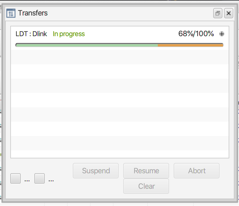
Figure 18 - Example of an LDT in progress. To highlight the Suspend, Resume and Abort options, the Operator must click on the LDT of interest.
3.2.1 Important Notes on LDTs Operations
Only one transfer should be requested at a time. While more than one transfer can progress in parallel the downlink efficiency is reduced when more than one transfer is on-going at the one time.
Other TCs can be sent while an LDT continues. Therefore, in the EIR-OPS-003: Start a Communication Pass procedure, a step is included to start (or resume) an LDT prior to proceeding with the plans for the pass.
Transfers will continue until:
they are completed
the end of a communication pass, at which point MCS will automatically pause the transfer due to a TC timeout or
a TC is sent by the Operator to pause the transfer
Paused transfers need to be manually resumed (e.g. at the start of a pass, following the EIR-OPS-003: Start a Communication Pass procedure) via the ‘Resume’ button on the Transfer window. For very large data sets, multiple communication passes may be required to downlink all of the data and the transfer may have to be paused/resumed multiple times.
3.3 On-Board Storage
Data is stored on-board the spacecraft in Flash and MRAM memory.
On EIRSAT-1 there is 3.5MB of MRAM and 4GB of Flash memory available.
While MRAM memory is accessible by both the primary and failsafe images, Flash memory is only used by and accessible in the primary images. Therefore, Flash memory is used to store the non-critical data types, such as science data, as well as a large backlog of the more critical data types, including HK, TED, PASCAL, ADCS, etc. In addition, while in the primary images, a smaller backlog of this critical data is duplicated in MRAM storage. This is to ensure we have the most recent primary image data in case we unexpectedly end up in the failsafe image - we will want some data from when we were last in the primary image to help tell us why failsafe was booted!
Take away message:
While the primary images are operating, data is primarily being logged to Flash and so, data will primarily be downlinked from Flash. However, the primary images also store the more critical data to MRAM.
While the failsafe image is operating, data is ONLY being logged to MRAM. Given this (and given that the failsafe image cannot access Flash memory), data will be downlinked from MRAM while in failsafe.
3.4 Storage Channels & Downlink Logic
There are two types of storage channels in the OBSW, known as Circular and Linear channels.
For Circular Channels: The rows of the channel fill with data until the channel is full. Once full, each new row of data will be logged to the “end” of the channel and the oldest row of data at the “start” of the channel will be lost.
For Linear Channels: The rows of the channel fill with data until the channel is full. Once full, no new data will be logged to the channel until the channel is cleared, or “wiped”, of data via a TC from the GS.
For the different channel types, different logic is used to determine which rows of a channel the GS has left to downlink (i.e. what First row and Last row values to use when downlinking data). This logic is described in Sections 3.4.1 and 3.4.2. However, during a pass the Operator will not have time to perform these calculations. Therefore, the following Google sheet - ROW - has been provided to help the Operator to quickly determine this information.
3.4.1 Circular Channels
Operators will use the following steps to determine what rows of data are left to be downlinked from a circular storage channel given information from the previous communication pass where data was downlinked:
Get the
cdh.logging.XXXLogger.AbsRowsLoggedparameter to determine the total number of rows ever logged to the channel by the logger of interest, whereXXX= HK, TED, PASCAL, ADCS, etc.If
cdh.logging.XXXLogger.AbsRowsLogged<= the max. number of rows that the channel can hold (defined in Table 1 below), the row range yet to be downlinked is then…First row= the last row downlinked from this channel (which will be 0 if this is the first pass)LastRow<= thecdh.logging.XXXLogger.AbsRowsLoggedparameter (i.e. from step 1).
If
cdh.logging.XXXLogger.AbsRowsLogged> the max. number of rows that the channel can hold (defined in table 1 below), the row range yet to be downlinked is then…First row= the max. rows that the storage channel can hold + thecdh.logging.XXXLogger.AbsRowsLoggedparameter obtained in the last data downlink from this channel - thecdh.logging.XXXLogger.AbsRowsLoggedparameter from this pass (i.e. from step 1). If this sum <= 0, thenFirst row= 0.Last row= the max. number of rows that the channel can hold (defined in Table 1 below).
3.4.2 Linear Channels
Operators will use the following steps to determine what rows of data are left to be downlinked from a linear storage channel given information from the previous communication pass where data was downlinked:
Get the
cdh.logging.XXXLogger.AbsRowsLoggedparameter to determine the total number of rows ever logged to the channel by the logger of interest, whereXXX= HK, TED, PASCAL, ADCS, etc.The row range yet to be downlinked is then…
First row= the last row downlinked from this channel (which will be 0 if this is the first pass or if the channel has been wiped since the last pass)Last row= thecdh.logging.XXXLogger.AbsRowsLoggedparameter modulo (i.e. %) the max. number of rows that the channel can hold (defined in below).
Note
As time passes, the linear channel will fill and so, no new data will be logged to the channel until the channel is wiped. Therefore, after a number of passes, the GS will have eventually downlinked all data that has been stored in that channel. When this happens, FirstRow = LastRow and so, there will be no need to attempt a downlink from this channel until the channel is wiped via TC from the GS.
3.4.3 Channel Configurations
The following Google sheet - ROW - contains an up-to-date description on the storage channel structure implemented in the OBSW.
3.4.3 Data Downlink Considerations
During Nominal Operations, the different data packets logged on-board will be assigned different downlink priorities.
However, there will be many scenarios throughout the mission (in particular during LEOP) where these priorities will need to be varied. In these cases, the priority to downlink different data types will change based on 1) the current/recent state of the satellite (e.g. if we are in Commissioning Mode and the satellite is in Safe Mode due to low power, the PASCAL packet will take highest priority) and 2) the upcoming operation.
The daily downlink priority for a number of nominal and non-nominal scenarios are presented in this section but it is not an all-inclusive list of possible scenarios.
Scenario 1: Nominal Operations - No GRB data; No WBC data
For a nominal pass, some HK, some TED and some Event data should be downlinked to allow the health of the spacecraft to be continuously monitored. Given the small amount of data generated by EMOD, this data type will take next preference. The remainder of the downlink window will then be used to downlink GMOD data. In this scenario, it is assumed that no GMOD data with a GRB detection is still to be downlinked. Therefore, during this time, the GMOD data downlinked will be either; 1) background data from targeted periods of time that are centered around the time of the last GRB trigger; or 2) background data from arbitrary periods of time to be used for further analysis/calibration.
Scenario 2: Nominal Operations - GRB data; No WBC data
For a nominal pass, some HK, some TED and some Event data should be downlinked to allow the health of the spacecraft to be continuously monitored. Given the small amount of data generated by EMOD, this data type will take next preference. The remainder of the downlink window will then be used to downlink GMOD data. In the case where GMOD data with a GRB detection is to be downlinked, the downlink time allocated to GMOD data will be separated each day between GRB data (which may take a couple of days to downlink in full, depending on the characteristics of the burst) and background data around the time of the detection.
Scenario 3: Nominal Operations - No GRB data; WBC data
For a nominal pass, some HK, some TED and some Event data should be downlinked to allow the health of the spacecraft to be continuously monitored. Given the small amount of data generated by EMOD, this data type will take next preference. If the spacecraft has entered WBC Mode (previous or on-going), the on-board storage will contain WBC data. The remainder of the downlink window will then be used to downlink WBC data. In a case where both GMOD data with a GRB detection and WBC data are to be downlinked, Scenario 2 will take preference over Scenario 3.
Scenario 4: Non-Nominal Operations (e.g. following the Separation Sequence or when Safe Mode is entered)
For a pass during non-nominal operations, the downlink of HK, TED, Event, PASCAL and ADCS data will take preference. In these mission critical scenarios, GMOD, EMOD and WBC data will not be considered for downlink. The downlink of PASCAL or ADCS data will depend on the anomalies identified during these mission critical scenarios and the team/operators will need to decide on what data to be downlinked.
3.5 EIR_OPS Procedure Example
The Operational procedures in this manual all follow the same format, as presented in Figure 23, with the following sections:
Objective - The aim of the procedure
Introduction - Brief description of what the procedure will achieve
Procedure - Step by step guide of how to perform the telecommands/operations
Statement saying END OF PROCEDURE
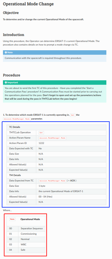
Figure 19 - Example Multi TC Procedure Format
Most steps in a procedure require you to use an Action (Section 2.1) or Parameter (Section 2.2). The table in the blue box in Figure 19 is filled out for any action or parameter that is used in a procedure step. The table has two main sections TC Details which contains the telecommand details and TM Details which states if a TM is expected and what the content should be.
- TC Details:
MCS Operation - Gives the operation (
Get,Set,Downlink,UplinkorQuery) that is to be selectedAction/Param Name - This contains the name of the action/parameter and the path to follow in the SCDB to get to the action/parameter
Action/Param ID - The unique numeric ID which is used to identify it to the onboard software. The ID can be found in lower left box in MCS.
Data Expected with TC - Yes if data is expected, No if not.
Data Size - The type and size of the data
Data Info - This depends on the operation, it could be the value you will set a parameter to, or the first and last row of data to uplink or down link or as in the example there could be no data as you are getting the parameter value.
Allowed Values - The allowed values for the parameter
Expected Values - The expected value(s) for the parameter
- TM Details:
Data Expected from TC - ACK or parameter name + ACK
Data Size - The type and size of the data
Data Info - What parameter is expected, in Figure 23, the parameter
Modeis expected to be returnedAllowed Data Values - The allowed values for the parameter being returned
Expected Values - The expected value(s) for the parameter
Also included in the step-by-step procedures will be additional knowledge required for completing the operations in the procedure. In Figure 19, there is a table (red box) explaining what the allowed data values mean for this operation.
Other additional knowledge will also be presented in blue Note boxes as in the Introduction Section in Figure 19 and green Important boxes as in the Procedure section. Notes will contain extra information on the operation being performed. Important boxes will contain vital information for the operation or what to do if there are issues encountered when performing the operation.
There is also Caution and Warning boxes in the step-by-step procedures, as in Figure 20. These will notify the Operator of issues that could cause errors and what to avoid in the operation being performed.
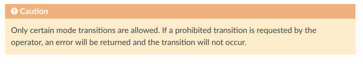
Figure 20 - Example Caution in Multi TC Procedure
4. Operator Tips
This section provides additional non-critical information/tips for Operators that may be useful to know when working with MCS and the procedures.
1. Multiple parameters and actions can be opened by the Operator in the MCS GUI at any one time. As passes can be quick and MCS can be cumbersome, it is recommended that the Operator have the parameters/actions open and ready to go prior to the pass, when possible (i.e. when the Operator has a clear procedure for what they want to do). It can be difficult to manage action and parameter windows when multiple windows are open. Therefore, make use of MCS’s Layouts and window positioning/drag-and-drop feature.
Layouts are located in the Mission Explorer window under connections. Layouts for regularly used procedures e.g. EIR-OPS-003: Start a Communication Pass will be available in the Layouts drop down menu, as shown in Figure 21.
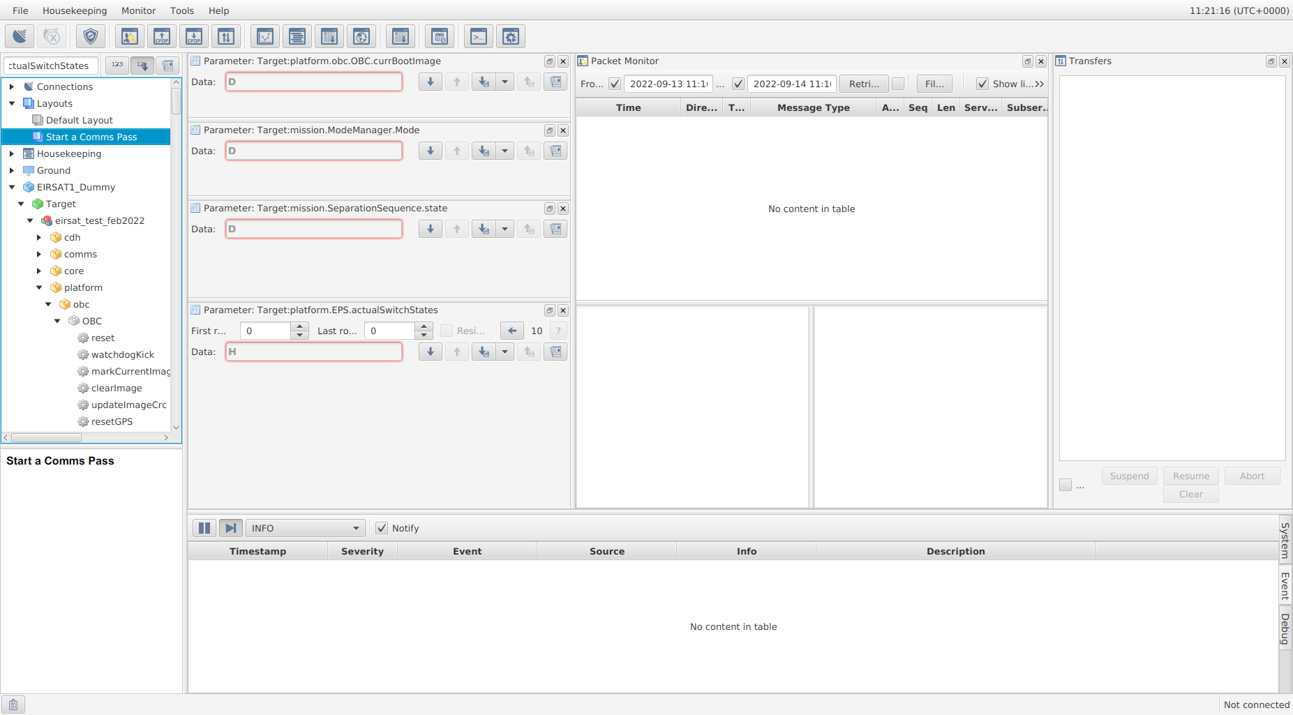
Figure 21 - Start a Communications Pass Layout
A new layout can be created by right clicking Layouts in the Mission Explorer window in MCS, as shown in Figure 22. This will just contain the Mission Explorer and System/Debug/Console windows by default. The Packet Monitor, Transfer window and any parameters required for the procedure should be opened and can be positioned using the drag-and-drop feature, as shown in Figure 23.
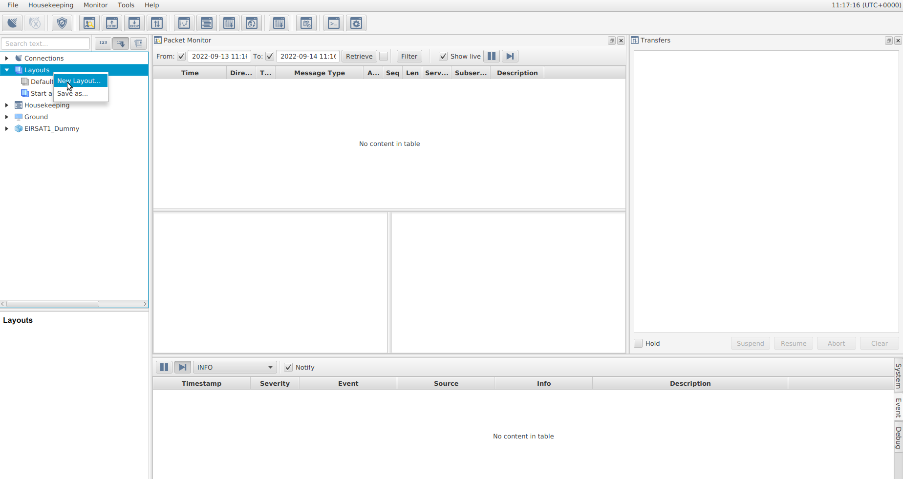
Figure 22 - Create new layout in MCS
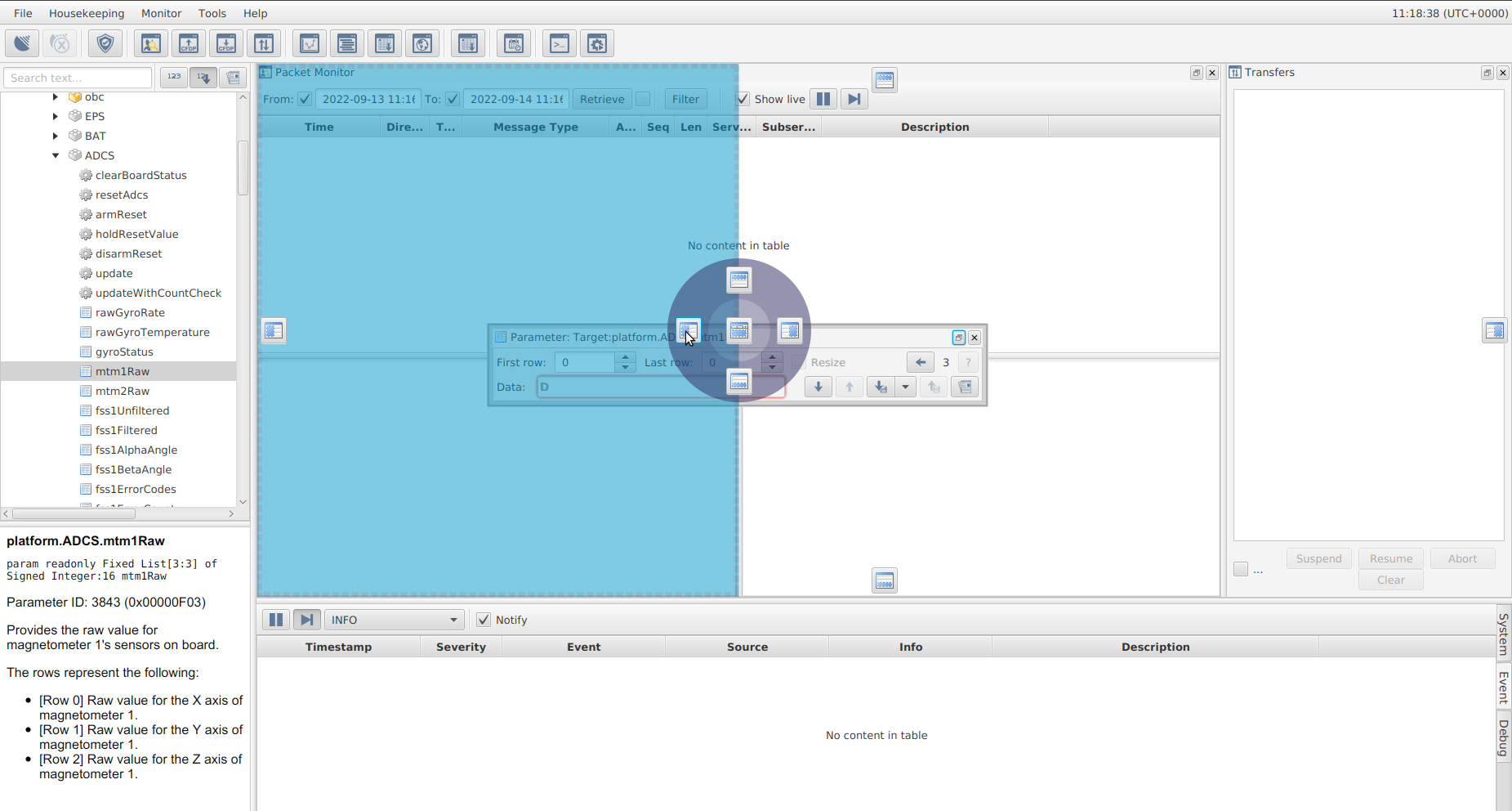
Figure 23 - Drag-and-drop feature to position windows and parameters in MCS Layout
2. When MCS is opened, you may notice that (sometimes) data remains in the Packet Monitor and Event Console windows from a previous session. To remove this data from the display, right click on the each of the displays and select the ‘Clear’ option.
3. Note that in the data field of action/parameter windows (see Figure 21), there is a ‘H’ symbol. The Operator can click on this symbol to change the numbering of the get/set data to be in a hex, decimal, binary and (when applicable) string format as shown in Figure 28.
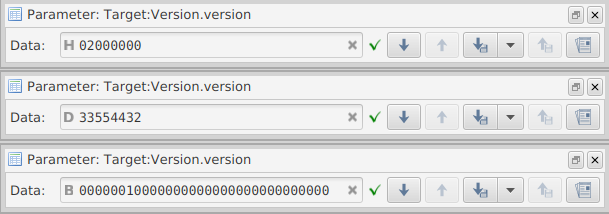
Figure 21 - Example of a Get for the same parameter but with MCS showing hex (top), decimal (middle) and binary (bottom) numbering.
4. When unsure of the data length to be sent with a Set TC, the Operator should always Get the parameter first and then edit the parameter value in the data field.
5. EIR_OPS
Note
Any questions on the above sections should be directed to the Operations Engineers, David Murphy and Gabriel Finneran.
Once you are comfortable with the information provided in the previous sections, the EIR_OPS Operational Procedures can be accessed from the links provided here -
- Operational Procedures
- EIR-OPS-002: Pre-Communication Pass Checklist
- EIR-OPS-003: Start a Communication Pass
- EIR-OPS-004: Initial AOS
- EIR-OPS-005: Failsafe at Initial AOS
- EIR-OPS-006: Commissioning
- EIR-OPS-007: Operational Mode Change
- EIR-OPS-008: ADCS Mode Change
- EIR-OPS-009: Enable TC Authentication
- EIR-OPS-011: Downlink Data From Storage
- EIR-OPS-012: Set Up Nominal Operations
- EIR-OPS-013: Storage Channel Operations
- EIR-OPS-015: Configure Data Logging
- EIR-OPS-016: Upload Payload Image
- EIR-OPS-017: Rewrite Payload Firmware
- EIR-OPS-018: Rewrite CPLD Firmware
- EIR-OPS-019: Reset/Power-cycle a Payload
- EIR-OPS-020: GMOD Configuration
- EIR-OPS-021: GMOD Experiment Set Up
- EIR-OPS-021A: GMOD Rapid Experiment Set Up
- EIR-OPS-022: EMOD Configuration
- EIR-OPS-023: Upload OBC Image
- EIR-OPS-024: Boot Into OBC Image
- EIR-OPS-025: Safe Mode Entered
- EIR-OPS-026: Low Battery Fault Analysis
- EIR-OPS-027: Reboot Fault Analysis
- EIR-OPS-028: High Rotation Rate Fault Analysis
- EIR-OPS-029: Failsafe Entered
- EIR-OPS-030: Power-cycle the Spacecraft
- EIR-OPS-031: DTMF Reboot
- EIR-OPS-032: Separation Sequence Restarted
- EIR-OPS-033: Enable/Disable RF Transmission
- EIR-OPS-034: NACK/Timeout/Unexpected TM
- EIR-OPS-035: Configure the FDIR Systems
- EIR-OPS-036: Downlink GRB Trigger Data
- EIR-OPS-037: Set-Up a TimeAction
- EIR-OPS-038: WBC Experiment Set Up
- EIR-OPS-039: WBC Monitor Transition to Commissioning Mode
- EIR-OPS-040: Updating the ADCS Configuration File
- Parameter Accessors (Gets/Sets)
- Action Accessors (Invokes)
- Events