EIR-OPS-006.10: GMOD Operations
Objective
To perform a first-time test of GMOD experiment operations following launch.
Introduction
In this procedure, GMOD experiment operations will be tested for the first time following launch by putting the payload into Experiment Mode and then downlinking and assessing the resulting experiment data.
Procedure
This procedure contains a number of sub-procedures as follows:
Note
A communication window is required for each of these sub-procedures.
A. Power On and Initial Checks
Important
You are about to send the first TC of this procedure - Have you completed the EIR-OPS-003: Start a Communication Pass procedure? A Communication Pass must be started prior to carrying out the operations planned for the pass. Don’t forget to open and set up the parameters/actions that will be used during the pass in MCS before the pass begins!
A.1.
Invokethe actionplatform.EPS.TurnOnGMODto turn ON GMOD.
TC Details |
|
MCS Operation |
|
Action/Param Name |
|
Data Expected with TC |
No |
TM Details |
|
Data Expected from TC |
No ( + ACK ) |
A.2.
Getthe parameterplatform.EPS.actualSwitchStateswithFirst row= 0 andLast row= 9 to assess whether GMOD is now on.Ensure that PDMs 3, 6 and 9/rows 2, 5 and 8 are ON/1.
Warning
PDM 8 is drawing parasitic power. Therefore, when you Get the platform.EPS.actualSwitchStates parameter it will always read as ON/1 even when it is powered OFF.
TC Details |
|
MCS Operation |
|
Action/Param Name |
|
Data Expected with TC |
|
Data Size |
2 bytes, 2 bytes |
Data Info |
The first and last rows/indexes of the parameter to get |
Allowed Value(s) |
0 - 9, 0 - 9 |
Expected Value(s) |
0, 9 |
TM Details |
|
Data Expected from TC |
|
Data Size |
List[0:9] of booleans |
Data Info |
If |
Allowed Value(s) |
0,0,0,0,0,0,0,0,0,0 (all OFF) - 1,1,1,1,1,1,1,1,1,1 (all ON) |
Expected Value(s) |
X,X,1,X,X,1,X,X,1,X (PDMs 3, 6 + 9 = 1. Other PDMs may be 0 or 1) |
A.3.
Getthe parameterpayload.GMOD.FirmwareVersionto further verify that GMOD is now on.Ensure the expected firmware version (i.e. version of firmware programmed onto the MSP during pre-launch preparations) is returned.
TC Details |
|
MCS Operation |
|
Action/Param Name |
|
Data Expected with TC |
No |
TM Details |
|
Data Expected from TC |
|
Data Size |
2 bytes |
Data Info |
Version of the firmware currently running on the GMOD MSP |
Allowed Value(s) |
0000 - FFFE |
Expected Value(s) |
Version of firmware programmed onto the MSP during pre-launch prep. |
A.4.
Getthe parameterpayload.GMOD.GMODModeto assess whether GMOD is operating in the expected mode following power on.Ensure Idle Mode/1 is returned.
TC Details |
|
MCS Operation |
|
Action/Param Name |
|
Data Expected with TC |
No |
TM Details |
|
Data Expected from TC |
|
Data Size |
Int4 |
Data Info |
Current operational mode of GMOD |
Allowed Value(s) |
1 - 5 |
Expected Value |
1 |
Where…
|
Mode |
|---|---|
1 |
Idle |
2 |
Experiment |
3 |
CPLD Programme |
4 |
Safe |
5 |
Experiment16 |
A.5.
Getthe parameterpayload.GMOD.ResetCounterto determine the number of times the GMOD payload has reset since the MSP was last programmed.Assess whether the value is as expected given the number of MSP power ONs since pre-launch preparations/programming.
TC Details |
|
MCS Operation |
|
Action/Param Name |
|
Data Expected with TC |
No |
TM Details |
|
Data Expected from TC |
|
Data Size |
1 byte |
Data Info |
Number of resets since the firmware was last programmed |
Allowed Value(s) |
0 - 127 |
A.6.
Getthe parameterpayload.GMOD.LastResetTypeto determine the most recent type(s) of GMOD reset(s) that have occurred.Continue to get this parameter until 0 is returned.
TC Details |
|
MCS Operation |
|
Action/Param Name |
|
Data Expected with TC |
No |
TM Details |
|
Data Expected from TC |
|
Data Size |
1 byte |
Data Info |
Last GMOD reset type(s) |
Allowed Value(s) |
00 - 2E |
Where…
|
Reset Type |
|---|---|
02 |
Brownout |
04 |
Unknown |
06 |
SW reboot |
14 |
SW reboot |
16 |
Watchdog reset |
B. Initialise GMOD Generating Data
B.1.
Getthepayload.GMOD.SyncTimeStatusparameter which indicates whether syncing of GMOD’s time from the OBC’s time is still in progress (0), a success (1), a failure (2 or 7) or yet to be synced (3).Ensure 3 (i.e. the initialisation value) is returned.
TC Details |
|
MCS Operation |
|
Action/Param Name |
|
Data Expected with TC |
No |
TM Details |
|
Data Expected from TC |
|
Data Size |
bit3 |
Data Info |
Status of time synchronisation between GMOD and OBC |
Allowed Value(s) |
0, 1, 2, 3, 7 |
Expected Value |
3 |
B.2.
Getthepayload.GMOD.MSPCoarseTimeparameter which returns the MSP’s current coarse time value.
TC Details |
|
MCS Operation |
|
Action/Param Name |
|
Data Expected with TC |
No |
TM Details |
|
Data Expected from TC |
|
Data Size |
4 bytes |
Data Info |
Coarse time counter from MSP |
Allowed Value(s) |
0 00000000 - FFFFFFFF (hex) |
Expected Value |
> 0 |
B.3.
Invokethepayload.GMOD.SyncTimeaction which synchronises GMOD’s coarse time clock with the OBC’s time.
TC Details |
|
MCS Operation |
|
Action/Param Name |
|
Data Expected with TC |
No |
TM Details |
|
Data Expected from TC |
No ( + ACK ) |
B.4.
Getthepayload.GMOD.SyncTimeStatusparameter which indicates whether syncing of GMOD’s time from the OBC’s time is still in progress (0), a success (1), a failure (2 or 7) or yet to be synced (3).Ensure 1 (i.e. the success value) is returned.
TC Details |
|
MCS Operation |
|
Action/Param Name |
|
Data Expected with TC |
No |
TM Details |
|
Data Expected from TC |
|
Data Size |
bit3 |
Data Info |
Status of time synchronisation between GMOD and OBC |
Allowed Value(s) |
0, 1, 2, 3, 7 |
Expected Value |
1 |
B.5.
Getthepayload.GMOD.MSPCoarseTimeparameter which returns the MSP’s current coarse time value.Ensure the returned value is much larger than the value returned in Step B.2, indicating that GMOD’s time is now consistent with the OBC’s.
TC Details |
|
MCS Operation |
|
Action/Param Name |
|
Data Expected with TC |
No |
TM Details |
|
Data Expected from TC |
|
Data Size |
4 bytes |
Data Info |
Coarse time counter from MSP |
Allowed Value(s) |
00000000 - FFFFFFFF (hex) |
Expected Value |
Larger than the value returned in Step B.2 |
B.6.
Getthepayload.GMOD.BaudRateSetStatusparameter which indicates whether setting the MSP baud rate was successful.Ensure 3 (i.e. the initialisation value) is returned.
TC Details |
|
MCS Operation |
|
Action/Param Name |
|
Data Expected with TC |
No |
TM Details |
|
Data Expected from TC |
|
Data Size |
bit3 |
Data Info |
Status of setting MSP baud rate |
Allowed Value(s) |
0 (in progress), 1 (success), 2 (failure), 3 (init) |
Expected Value |
3 |
B.7.
Invokethepayload.GMOD.MSPBaudRateaction with action argument = 01F400 (hex), which corresponds to a baud rate of 128000 (dec), to set the serial baud rate at which GMOD transfers data over to the OBC.
TC Details |
|
MCS Operation |
|
Action/Param Name |
|
Data Expected with TC |
|
Data Size |
3 bytes |
Data Info |
Baud rate for serial communication |
Allowed Value(s) |
000000 - FFFFFF (hex) |
Expected Value(s) |
01F400 (hex) |
TM Details |
|
Data Expected from TC |
No ( + ACK ) |
B.8.
Getthepayload.GMOD.BaudRateSetStatusparameter which indicates whether setting the MSP baud rate was successful.Ensure 1 (i.e. the success value) is returned.
TC Details |
|
MCS Operation |
|
Action/Param Name |
|
Data Expected with TC |
No |
TM Details |
|
Data Expected from TC |
|
Data Size |
bit3 |
Data Info |
Status of setting MSP baud rate |
Allowed Value(s) |
0 (in progress), 1 (success), 2 (failure), 3 (init) |
Expected Value |
1 |
B.9.
Getthe parameterpayload.GMOD.RegErrStatusto read the value of the ERR_O pin on the ASIC, which indicates if there are parity errors in registers.
Note
The value of this parameter should be roughly noted for later comparison with the same parameter following writing the registers to SIPHRA (i.e. Step B.16). The actual value may be gibberish at this time.
TC Details |
|
MCS Operation |
|
Action/Param Name |
|
Data Expected with TC |
No |
TM Details |
|
Data Expected from TC |
|
Data Size |
bit2 |
Data Info |
Value of the ERR_O pin on the ASIC |
Allowed Value(s) |
0 - 1 |
B.10.
Getthe parameterpayload.GMOD.ReadRegErrRegto read the individual register parity error statuses.
Note
The value of this parameter should be roughly noted for later comparison with the same parameter following writing the registers to SIPHRA (i.e. Step B.17). The actual value may be gibberish at this time.
TC Details |
|
MCS Operation |
|
Action/Param Name |
|
Data Expected with TC |
No |
TM Details |
|
Data Expected from TC |
|
Data Size |
4 bytes |
Data Info |
28-bit bitmap of boolean parity errors |
Allowed Value(s) |
00000000 - 0FFFFFFF |
B.11.
Getthe parameterpayload.GMOD.InitGMODConstantCurrValueto assess the DACA value that controls the MBias current.Ensure that 0862 (hex) is returned.
TC Details |
|
MCS Operation |
|
Action/Param Name |
|
Data Expected with TC |
No |
TM Details |
|
Data Expected from TC |
|
Data Size |
2 bytes |
Data Info |
Initialisation value for GMOD constant current |
Allowed Value(s) |
0000 - FFFF (hex) |
Expected Value |
0862 (hex) |
B.12.
Downlinkthe SIPHRA registers to be set using the parameterpayload.GMOD.InitASICRegBufferwithFirst row= 0 andLast row= 27.Confirm the contents of the downliked file match the image below.
TC Details |
|
MCS Operation |
|
Action/Param Name |
|
Data Expected with TC |
|
Data Size |
2 bytes, 2 bytes |
Data Info |
The first and last rows/indexes of the parameter to get |
Allowed Value(s) |
0 - 27, 0 - 27 (dec) |
Expected Value(s) |
0, 27 (dec) |
TM Details |
|
Data Expected from TC |
|
Data Size |
112 bytes |
Data Info |
ASIC register values to be set as part of the |
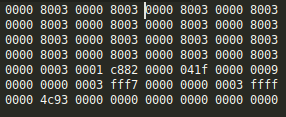
Figure 1 - Expected values for GMOD.InitASICRegBuffer
B.13.
Invokethe actionpayload.GMOD.InitialiseGMOD.
TC Details |
|
MCS Operation |
|
Action/Param Name |
|
Data Expected with TC |
No |
TM Details |
|
Data Expected from TC |
No ( + ACK ) |
Note
Currently this function: 1) Sets the ConstantCurrValue parameter (to the InitGMODConstantCurrValue parameter), 2) Sets the ConstantCurrEnable parameter to TRUE, 3) Toggles the ASICResetPin OFF and then ON, and 4) Writes the InitASICRegBuffer data to the ASIC reg table on the GMOD MSP. Each of these steps will only proceed if the previous step succeeded.
B.14.
Invokethe actionpayload.GMOD.writeRegToSIPHRAto write the contents of the ASIC register table on the MSP to the SIPHRA registers.
TC Details |
|
MCS Operation |
|
Action/Param Name |
|
Data Expected with TC |
No |
TM Details |
|
Data Expected from TC |
No ( + ACK ) |
B.15.
Getthe parameterpayload.GMOD.WriteRegStatusto confirm that the writes to SIPHRA were successful.Ensure 1 (i.e. success) is returned.
TC Details |
|
MCS Operation |
|
Action/Param Name |
|
Data Expected with TC |
No |
TM Details |
|
Data Expected from TC |
|
Data Size |
bit3 |
Data Info |
Successful = 1, In Progress = 0, Failed = 2 |
Allowed Value(s) |
0, 1, 2 |
Expected Value |
1 |
B.16.
Getthe parameterpayload.GMOD.RegErrStatusto read the value of the ERR_O pin on the ASIC, which indicates if there are parity errors in registers.Ensure 0 is returned (i.e. ensure the parameter has updated since Step B.9).
TC Details |
|
MCS Operation |
|
Action/Param Name |
|
Data Expected with TC |
No |
TM Details |
|
Data Expected from TC |
|
Data Size |
bit2 |
Data Info |
Value of the ERR_O pin on the ASIC |
Allowed Value(s) |
0, 1 |
Expected Value |
0 |
B.17.
Getthe parameterpayload.GMOD.ReadRegErrRegto read the individual register parity error statuses.Ensure all 0s are returned (i.e. ensure the parameter has updated since Step B.10).
TC Details |
|
MCS Operation |
|
Action/Param Name |
|
Data Expected with TC |
No |
TM Details |
|
Data Expected from TC |
|
Data Size |
4 bytes |
Data Info |
28-bit bitmap of boolean parity errors |
Allowed Value(s) |
00000000 - 0FFFFFFF (hex) |
Expected Value |
00000000 |
B.18.
Setthe parameterpayload.GMOD.BiasOffsetValueto 08CC (hex).
TC Details |
|
MCS Operation |
|
Action/Param Name |
|
Data Expected with TC |
|
Data Size |
2 bytes |
Data Info |
Bias Offset Value |
Allowed Value(s) |
0000 - 0FFF (hex) |
Expected Value(s) |
08CC (hex) |
TM Details |
|
Data Expected from TC |
No ( + ACK ) |
B.19.
Confirm the
Setin the previous step with aGet(i.e. confirm the value was set successfully).
B.20.
Setthe parameterpayload.GMOD.boostConverterEnableto 1 (i.e. enabled).
TC Details |
|
MCS Operation |
|
Action/Param Name |
|
Data Expected with TC |
|
Data Size |
Boolean |
Data Info |
Boost Converter is Disabled (0) or Enabled (1) |
Allowed Value(s) |
0, 1 |
Expected Value(s) |
1 |
TM Details |
|
Data Expected from TC |
No ( + ACK ) |
B.21.
Confirm the
Setin the previous step with aGet(i.e. confirm the value was set successfully).
B.22.
Setthe parameterpayload.GMOD.biasOffsetEnableto 1 (i.e. enabled).
TC Details |
|
MCS Operation |
|
Action/Param Name |
|
Data Expected with TC |
|
Data Size |
Boolean |
Data Info |
Bias Offset is Disabled (0) or Enabled (1) |
Allowed Value(s) |
0, 1 |
Expected Value(s) |
1 |
TM Details |
|
Data Expected from TC |
No ( + ACK ) |
B.23.
Confirm the
Setin the previous step with aGet(i.e. confirm the value was set successfully).
B.24.
Getthe parameterpayload.GMOD.LastPageSumAddrseveral times, with ~3 seconds between each TC, to read the memory address of the last summed channel TTE page stored to GMOD’s flash memory.Ensure the parameter value is NOT changing between TCs, which confirms that GMOD is not currently generating data.
TC Details |
|
MCS Operation |
|
Action/Param Name |
|
Data Expected with TC |
No |
TM Details |
|
Data Expected from TC |
|
Data Size |
3 bytes |
Data Info |
Memory address for the last stored sum channel TTE page |
Allowed Value |
000000 - 007FFF (hex) |
Expected Value(s) |
Not changing between TCs |
B.25.
Getthe parameterpayload.GMOD.GMODModeto assess what mode GMOD is operating in.
TC Details |
|
MCS Operation |
|
Action/Param Name |
|
Data Expected with TC |
No |
TM Details |
|
Data Expected from TC |
|
Data Size |
Int4 |
Data Info |
Current operational mode of GMOD |
Allowed Value(s) |
1 - 5 |
Where…
|
Mode |
|---|---|
1 |
Idle |
2 |
Experiment |
3 |
CPLD Programme |
4 |
Safe |
5 |
Experiment16 |
B.26.
If GMOD is not operating in Experiment Mode (i.e. if
GMODMode!= 02),SettheGMODModeparameter to 2 now.
TC Details |
|
MCS Operation |
|
Action/Param Name |
|
Data Expected with TC |
Yes |
Data Size |
Int4 |
Data Info |
Mode of GMOD |
Allowed Value(s) |
01, 02, 03, 04, 05 |
Expected Value(s) |
02 |
TM Details |
|
Data Expected from TC |
No ( + ACK ) |
B.27.
Confirm the
Setin the previous step with aGet(i.e. confirm the value was set successfully).
Important
If GMOD is being left on and generating data for a long period of time, the GMOD team should be consulted about configuring the S/C to stop GMOD generating data while passing through the South Atlantic Anomaly (SAA), a region with high levels of radiation. A TimeAction component can be used to invoke an action/set a parameter based on time. The EIR-OPS-037: Set-Up a TimeAction procedure can be followed to set up two TimeActions, one to set the payload.GMOD.GMODMode to Idle (0x01) prior to SAA entry and one to set the payload.GMOD.GMODMode to Experiment (0x02) at SAA exit so GMOD starts generating data again.
B.28.
Getthe parameterpayload.GMOD.LastPageSumAddrseveral times, with ~3 seconds between each TC, to read the memory address of the last summed channel TTE page stored to GMOD’s flash memory.This time, ensure the parameter value is changing, which confirms that GMOD is now generating data.
Record the last value returned from these gets for use in Section C.
TC Details |
|
MCS Operation |
|
Action/Param Name |
|
Data Expected with TC |
No |
TM Details |
|
Data Expected from TC |
|
Data Size |
3 bytes |
Data Info |
Memory address for the last stored sum channel TTE page |
Allowed Value |
000000 - 007FFF (hex) |
Expected Value(s) |
Changing between TCs |
C. Set Up Streaming Data to the OBC
Parameter Name |
Data Size |
Data Info |
Allowed Values |
|---|---|---|---|
LCBinWidth |
uint16 |
The bin width (in milliseconds) to be used for the ‘normal’/logged lightcurve buffer. |
1-65535 (dec) |
LCADCEventLims |
uint16 [2] |
The upper and lower limits to be used when assessing whether ADC event data should be added to the ‘normal’/logged LC buffer. Row 0 is the lower limit and row 1 is the upper limit. |
0-65535 (dec) |
SpecLowerADCBinLim |
uint16 |
The lower limit to be used when assessing whether ADC event data should be added to the ‘normal’/logged spectrum buffer. |
0 - 4095 (dec) |
SpecADCBinWidth |
uint8 |
The bin width (in ADC channels) to be used for the logged spectrum buffer. |
1 - 16 (dec) |
SpecIntTime |
uint16 |
The integration time (in seconds) to be used for the ‘normal’/logged spectrum buffer. |
1-65535 (dec) |
C.1.
Prior to setting up streaming of data from GMOD to the OBC, the parameters listed in the table above must be reviewed (e.g. via
GetTCs and/or previous pass notes), and may need to be changed (i.e. via aGet-Set-Get).If the GMOD Team have specified that one or more of the parameters in the table above needs to be configured, follow Steps C.1-C.3 for each of the parameters to be changed.
Getthe parameterpayload.GMOD.XXXX, where XXXX is the parameter name from the table above.
TC Details |
|
MCS Operation |
|
Action/Param Name |
|
Data Expected with TC |
Parameter-dependant |
TM Details |
|
Data Expected from TC |
|
C.2.
If the parameter value is not as desired,
Setthepayload.GMOD.XXXXparameter to the desired value now.
TC Details |
|
MCS Operation |
|
Action/Param Name |
|
Data Expected with TC |
Yes |
TM Details |
|
Data Expected from TC |
No ( + ACK ) |
C.3.
Confirm the
Setin the previous step with aGet(i.e. confirm the value was set successfully).
C.4.
Getthe parameterpayload.GMOD.LastPageSumAddrRxseveral times, with ~3 seconds between each TC, to read the memory address of the last summed channel TTE page received by the OBC from GMOD.Ensure the parameter value is NOT changing between TCs, which confirms that the OBC is not currently receiving this data type from GMOD.
TC Details |
|
MCS Operation |
|
Action/Param Name |
|
Data Expected with TC |
No |
TM Details |
|
Data Expected from TC |
|
Data Size |
2 bytes |
Data Info |
Updates with the memory address of the last summed channel TTE page received by the OBC from the MSP |
Allowed Value |
000000 - 007FFF (hex) |
Expected Value(s) |
Not changing between TCs |
C.5.
Invokethe actionpayload.GMOD.StreamSumEnablewith the action argument set as thepayload.GMOD.LastPageSumAddrparameter value noted in Step B.28.
TC Details |
|
MCS Operation |
|
Action/Param Name |
|
Data Expected with TC |
|
Data Size |
2 bytes |
Data Info |
GMOD flash memory address to stream data from |
Allowed Value(s) |
000000 - 007FFF (hex) |
Expected Value(s) |
|
TM Details |
|
Data Expected from TC |
No ( + ACK ) |
C.6.
Getthe parameterpayload.GMOD.LastPageSumAddrRxseveral times, with ~3 seconds between each TC, to read the memory address of the last summed channel TTE page received by the OBC from GMOD.This time, ensure the parameter value is changing, which confirms that the OBC is now receiving this data type from GMOD.
TC Details |
|
MCS Operation |
|
Action/Param Name |
|
Data Expected with TC |
No |
TM Details |
|
Data Expected from TC |
|
Data Size |
uint16 |
Data Info |
Updates with the memory address of the last summed channel TTE page received by the OBC from the MSP |
Allowed Value |
000000 - 007FFF (hex) |
Expected Value(s) |
Changing between TCs |
C.7.
Querythe parametercore.Storage.channelContentwithParameter Index in Blockset to 25 (dec).Send this TC several times with ~30 seconds between each TC.
Ensure that the TM returned is increasing, which confirms that GMOD data is being stored by the OBC.
TC Details |
|
MCS Operation |
|
Action/Param Name |
|
Data Expected with TC |
|
Data Size |
4 bytes |
Data Info |
Channel ID |
Allowed Value(s) |
1 - 88 (dec) |
Expected Value(s) |
25 (dec) |
TM Details |
|
Data Expected from TC |
Number of rows in GMOD’s Sum TTE storage channel ( + ACK ) |
Data Size |
4 bytes |
Data Info |
Number of rows in GMOD’s Sum TTE storage channel |
Allowed Value |
0 - 65535 (dec) |
Expected Value(s) |
Increasing |
D. OBC Lightcurve and Spectrum Generation
D.1.
Invokethe actionpayload.GMOD.ResetSerRxStateto reset the OBC’s ‘RxState’ for parsing of incoming serial data from GMOD.
TC Details |
|
MCS Operation |
|
Action/Param Name |
|
Data Expected with TC |
No |
TM Details |
|
Data Expected from TC |
No ( + ACK ) |
D.2.
Invokethe actionspayload.GMOD.ResetLCBufferandpayload.GMOD.ResetSpecBufferto reset the OBC’s lightcurve and spectrum buffers, respectively.Start a timer.
TC Details |
|
MCS Operation |
|
Action/Param Name |
|
Data Expected with TC |
No |
TM Details |
|
Data Expected from TC |
No ( + ACK ) |
TC Details |
|
MCS Operation |
|
Action/Param Name |
|
Data Expected with TC |
No |
TM Details |
|
Data Expected from TC |
No ( + ACK ) |
D.3.
Querythe parametercore.Storage.channelContentwithParameter Index in Blockset to 25 (dec).Take note of the TM returned (as the number of rows of GMOD Sum TTE data) for use in later steps/passes.
TC Details |
|
MCS Operation |
|
Action/Param Name |
|
Data Expected with TC |
|
Data Size |
4 bytes |
Data Info |
Channel ID |
Allowed Value(s) |
1 - 88 (dec) |
Expected Value(s) |
25 (dec) |
TM Details |
|
Data Expected from TC |
Number of rows in GMOD’s Sum TTE storage channel ( + ACK ) |
Data Size |
4 bytes |
Data Info |
Number of rows in GMOD’s Sum TTE storage channel |
Allowed Value |
0 - 65535 (dec) |
D.4.
Querythe parametercore.Storage.channelContentwithParameter Index in Blockset to 21 (dec).Take note of the TM returned (as the number of rows of GMOD lightcurves) for use in later steps/passes.
TC Details |
|
MCS Operation |
|
Action/Param Name |
|
Data Expected with TC |
|
Data Size |
4 bytes |
Data Info |
Channel ID |
Allowed Value(s) |
1 - 88 (dec) |
Expected Value(s) |
21 (dec) |
TM Details |
|
Data Expected from TC |
Number of rows in GMOD’s lightcurve storage channel ( + ACK ) |
Data Size |
4 bytes |
Data Info |
Number of rows in GMOD’s lightcurve storage channel |
Allowed Value |
0 - 65535 (dec) |
D.5.
Querythe parametercore.Storage.channelContentwithParameter Index in Blockset to 22 (dec).Take note of the TM returned (as the number of rows of GMOD spectra) for use in later steps/passes.
TC Details |
|
MCS Operation |
|
Action/Param Name |
|
Data Expected with TC |
|
Data Size |
4 bytes |
Data Info |
Channel ID |
Allowed Value(s) |
1 - 88 (dec) |
Expected Value(s) |
22 (dec) |
TM Details |
|
Data Expected from TC |
Number of rows in GMOD’s spectrum storage channel ( + ACK ) |
Data Size |
4 bytes |
Data Info |
Number of rows in GMOD’s spectrum storage channel |
Allowed Value |
0 - 65535 (dec) |
D.6.
Continue with this procedure in a later pass, when >25 minutes has elapsed on the timer that was initiated in Step D.2.
Other, non-GMOD-related procedures may proceed in parallel while waiting.
D.7.
Again,
Querythe parametercore.Storage.channelContentwithParameter Index in Blockset to 25 (dec).Ensure the TM has increased compared to the TM returned in Step D.3, indicating that new GMOD Sum TTE data has been generated, streamed and logged since Step D.3.
TC Details |
|
MCS Operation |
|
Action/Param Name |
|
Data Expected with TC |
|
Data Size |
4 bytes |
Data Info |
Channel ID |
Allowed Value(s) |
1 - 88 (dec) |
Expected Value(s) |
25 (dec) |
TM Details |
|
Data Expected from TC |
Number of rows in GMOD’s Sum TTE storage channel ( + ACK ) |
Data Size |
4 bytes |
Data Info |
Number of rows in GMOD’s Sum TTE storage channel |
Allowed Value |
0 - 65535 (dec) |
D.8.
Querythe parametercore.Storage.channelContentwithParameter Index in Blockset to 21 (dec).Ensure the TM has increased compared to the TM returned in Step D.4, indicating that new lightcurves have been generated since Step D.4.
TC Details |
|
MCS Operation |
|
Action/Param Name |
|
Data Expected with TC |
|
Data Size |
4 bytes |
Data Info |
Channel ID |
Allowed Value(s) |
1 - 88 (dec) |
Expected Value(s) |
21 (dec) |
TM Details |
|
Data Expected from TC |
Number of rows in GMOD’s lightcurve storage channel ( + ACK ) |
Data Size |
4 bytes |
Data Info |
Number of rows in GMOD’s lightcurve storage channel |
Allowed Value |
0 - 65535 (dec) |
D.9.
Querythe parametercore.Storage.channelContentwithParameter Index in Blockset to 22 (dec).Ensure the TM has increased compared to the TM returned in Step D.5, indicating that new lightcurves have been generated since Step D.5.
TC Details |
|
MCS Operation |
|
Action/Param Name |
|
Data Expected with TC |
|
Data Size |
4 bytes |
Data Info |
Channel ID |
Allowed Value(s) |
1 - 88 (dec) |
Expected Value(s) |
22 (dec) |
TM Details |
|
Data Expected from TC |
Number of rows in GMOD’s spectrum storage channel ( + ACK ) |
Data Size |
4 bytes |
Data Info |
Number of rows in GMOD’s spectrum storage channel |
Allowed Value |
0 - 65535 (dec) |
D.10.
Follow EIR-OPS-011: Downlink Data From Storage to downlink these newly-generated rows of data from channel IDs = 21, 22 and 25 (dec), with priority given to the OLDEST data.
Note
Downlinking this data will likely require multiple passes.
D.11.
When available, assess the data downlinked from GMOD and confirm with the GMOD Team that the experiment is generating the expected lightcurve and spectrum data from the raw TTE data.
E. Enable OBC Triggering
Important
This section should only be followed if the GMOD Team have confirmed that OBC Triggering can be enabled and have provided details on the parameters that need to be configured. The table below contains a list of the possible parameters that can be changed prior to enabling GRB Triggering. Steps E.1. to E.3. should be completed for each of the parameters that need to be set to a specific value before enabling GRB Triggering (Steps E.4. and E.5).
Parameter Name |
Data Size |
Data Info |
Allowed Values |
|---|---|---|---|
BkgWindowLen |
uint16 |
The number of triggering lightcurve buffer bins to be used when calculating the background signal strength. NOTE: BkgWindowLen/SigWindowLen should be an integer prior to proceeding with triggering checks (to allow for proper signal window scaling) and the BkgWindowLen set must be less than SigWindowOffset. |
1-65535 (dec) |
SigWindowLen |
uint16 |
The number of triggering lightcurve buffer bins to be used when calculating the signal strength. NOTE: BkgWindowLen/SigWindowLen should be an integer prior to proceeding with triggering checks (to allow for proper signal window scaling) and (SigWindowLen + SigWindowOffset + 1) must not exceed the max trigger buffer size |
1-65535 (dec) |
SigWindowOffset |
uint16 |
The number of triggering lightcurve buffer bins to offset when calculating the signal strength. NOTE: (SigWindowLen + SigWindowOffset + 1) must not exceed the max trigger buffer size |
1-65535 (dec) |
SigSquaredThreshold |
uint32 |
The square of the signal trigger threshold to be used for GRB trigger checks. |
|
TrigBinWidth |
uint16 |
The bin width (in milliseconds) to be used for the triggering lightcurve buffer. |
1-65535 (dec) |
TrigADCEventLims |
uint16 [2] |
The upper and lower limits to be used when assessing whether ADC event data should be considered valid for trigger checks. Row 0 is the lower limit and row 1 is the upper limit. |
0-65535 (dec) |
AllowedTrigTimeGap |
uint16 |
The allowed time gap (in millseconds) between TTEs for them to be assessed within the one light curve for triggering. |
0-65535 (dec) |
AllowedTrigElapsedTime |
unint32 |
The total elapsed time (in millseconds) allowed for one trigger. |
|
ProtectTimeAroundTrig |
uint16 |
Defines the amount of time in seconds before (row 0) and after (row 1) a trigger during which TTEs should be protected in a linear channel due the possibility of a GRB signal in the data. |
0-65535 (dec) |
TrigSpecTimeMultipliers |
uint8 [2] |
Multipliers used to define the start and integration times of trigger-associated spectrums, where Spectrum Start Time = Trigger Start Time - (Trigger Elapsed Time in seconds * [Row 0 of this Parameter]) AND where the Spectrum Integration Time = (Trigger Elapsed Time in microseconds * [Row 1 of this Parameter]). Note that Row 1 of this parameter must be greater than 0 and is initialised as 1. Additionally, given Row 0 (which defines the Spectrum Start Time), take care when setting Row 1, such that the spectrum generated actually includes the trigger. |
0/1-255 (dec) |
TrigLCTimeMultipliers |
uint8 [2] |
Multipliers used to define the start time and bin width of trigger-associated LCs, where LC Start Time = Trigger Start Time - (Trigger Elapsed Time in seconds * [Row 0 of this Parameter]) AND where the LC bin width = (Trigger Elapsed Time in milliseconds * [Row 1 of this Parameter])/number of bins. Note that Row 1 of this parameter must be greater than 0 and is initialised as 1. Additionally, given Row 0 (which defines the LC Start Time), take care when setting Row 1, such that the LC generated actually includes the trigger. |
0/1-255 (dec) |
TrigFoMSlope |
uint16 |
The negative slope to be used in the FoM function that determines the Delta SigSquared required to update the beacon buffers, where (Required Delta SigSquared) = (-TrigFoMSlope x Delta End Time) + (TrigFoMIntercept). |
0-65535 (dec) |
TrigFoMIntercept |
uint16 |
The y-intercept to be used in the FoM function that determines the Delta SigSquared required to update the beacon buffers, where (Required Delta SigSquared) = (-TrigFoMSlope x Delta End Time) + (TrigFoMIntercept). |
0-65535 (dec) |
E.1.
Prior to setting up OBC Triggering, the parameters listed in the table above must be reviewed (e.g. via
GetTCs and/or previous pass notes), and may need to be changed (i.e. via aGet-Set-Get).If the GMOD Team have specified that one or more of the parameters in the table above needs to be configured, follow Steps E.1-E.3 for each of the parameters to be changed.
Getthe parameterpayload.GMOD.XXXX, where XXXX is the parameter name from the table above.
TC Details |
|
MCS Operation |
|
Action/Param Name |
|
Data Expected with TC |
Parameter-dependant |
TM Details |
|
Data Expected from TC |
|
E.2.
If the parameter value is not as desired,
Setthepayload.GMOD.XXXXparameter to the desired value now.
TC Details |
|
MCS Operation |
|
Action/Param Name |
|
Data Expected with TC |
Yes |
TM Details |
|
Data Expected from TC |
No ( + ACK ) |
E.3.
Confirm the
Setin the previous step with aGet(i.e. confirm the value was set successfully).
E.4.
To now enable GRB Triggering,
Setthepayload.GMOD.GRBTriggeringEnabledparameter to 1.
TC Details |
|
MCS Operation |
|
Action/Param Name |
|
Data Expected with TC |
Yes |
Data Size |
bit1 |
Data Info |
Enable (1) or Disable (0) GRB Triggering |
Allowed Value(s) |
0 - 1 |
Expected Value(s) |
1 |
TM Details |
|
Data Expected from TC |
No ( + ACK ) |
E.5.
Confirm the
Setin the previous step with aGet(i.e. confirm the value was set successfully).
Important
Early in the mission, and possibly during the mission, the GRB trigger threshold may need to be modified (increased/decreased) based on the GMOD data downlinked. The GMOD team should be consulted before changing the trigger threshold.
F. Power Off GMOD
Important
The Operator may now choose to 1) turn off the GMOD payload and set it up again later via the EIR-OPS-021: GMOD Experiment Set Up procedure, 2) to leave GMOD powered on and experiment running as is, OR 3) leave GMOD powered on but reconfigure the experiment settings via the EIR-OPS-020: GMOD Configuration procedure. If the first option is preferred, the Operator should now proceed with Step F.1. to power off the GMOD payload. Otherwise, skip to Step F.5.
F.1.
Prior to power OFF, GRB triggering should be disabled. To do this,
Setthepayload.GMOD.GRBTriggeringEnabledparameter to 0.
TC Details |
|
MCS Operation |
|
Action/Param Name |
|
Data Expected with TC |
Yes |
Data Size |
bit1 |
Data Info |
Enable (1) or Disable (0) GRB Triggering |
Allowed Value(s) |
0 - 1 |
Expected Value(s) |
0 |
TM Details |
|
Data Expected from TC |
No ( + ACK ) |
F.2.
Confirm the
Setin the previous step with aGet(i.e. confirm the value was set successfully).
F.3.
Invokethe actionplatform.EPS.TurnOffGMODto turn OFF GMOD.
TC Details |
|
MCS Operation |
|
Action/Param Name |
|
Data Expected with TC |
No |
TM Details |
|
Data Expected from TC |
No ( + ACK ) |
F.4.
Getthe parameterplatform.EPS.actualSwitchStateswithFirst row= 0 andLast row= 9 to assess whether GMOD is now OFF.Ensure that PDMs 3, 6 and 9/rows 2, 5 and 8 are OFF/0.
Warning
It will take ~40 seconds for PDM 3 to return as OFF/0.
Warning
PDM 8 is drawing parasitic power. Therefore, when you Get the platform.EPS.actualSwitchStates parameter it will always read as ON/1 even when it is powered OFF.
TC Details |
|
MCS Operation |
|
Action/Param Name |
|
Data Expected with TC |
|
Data Size |
2 bytes, 2 bytes |
Data Info |
The first and last rows/indexes of the parameter to get |
Allowed Value(s) |
0 - 9, 0 - 9 |
Expected Value(s) |
0, 9 |
TM Details |
|
Data Expected from TC |
|
Data Size |
List[0:9] of booleans |
Data Info |
If |
Allowed Value(s) |
0,0,0,0,0,0,0,0,0,0 (all OFF) - 1,1,1,1,1,1,1,1,1,1 (all ON) |
Expected Value(s) |
X,X,0,X,X,0,X,X,0,X (PDMs 3, 6 + 9 = 0. Other PDMs may be 0 or 1) |
F.5.
The GMOD operational test has been completed. The Operator should now proceed with one of the sub-procedures listed in EIR-OPS-006: Commissioning that is yet to be completed.
Note
The sub-procedures listed in EIR-OPS-006: Commissioning do not necessarily need to be carried out in the order given. However, procedures ending in ‘Operation’ should only be completed after the relevant ‘Health Check’ procedure for that subsystem has been performed. The ‘EMOD Reprogramming’ procedure must also be performed prior to any EMOD activities. Lastly, ideally, payload operations should be the last item to consider in the commissioning of the spacecraft.
Alternatively, if all sub-procedures listed in EIR-OPS-006: Commissioning have been successfully completed, the Operator may now proceed to EIR-OPS-012: Set Up Nominal Operations .
END OF PROCEDURE